| Bloodhound Mk 2 | |
|---|---|
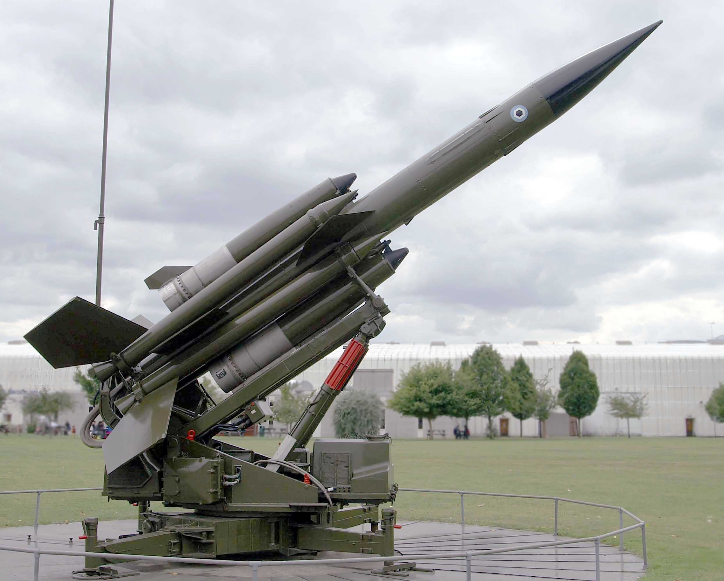 A Bloodhound missile at the RAF Museum, Hendon, London. | |
| Type | SAM |
| Place of origin | United Kingdom |
| Service history | |
| In service | 1958 (MK 1)/1964 (MK 2) - 1991 |
| Used by | See operators |
| Wars | - |
| Production history | |
| Designed | 1950s |
| Manufacturer | Bristol Aeroplane Co. |
| No. built | 783 |
| Variants | See variants |
| Specifications | |
| Mass | Overall: 2,270 kg (5,000 lb) |
| Length | Overall: 8.46 m (27 ft 9 in) |
| Diameter | Main body 54.6 cm (1 ft 9.5 in) |
| Warhead | Continuous-rod warhead |
Detonation mechanism | Proximity fuse |
|
| |
| Engine | 2× Ramjets, 4× solid fuel boosters |
| Wingspan | Overall: 2.83 m (9 ft 3 in) |
Operational range | 85 km |
| Maximum speed | Mach 2.7 |
Guidance system | Semi-active radar homing |
Steering system | Control surfaces |
Launch platform | Fixed installation |
The Bristol Bloodhound is a British surface-to-air missile developed during the 1950s as the UK's main air defence weapon, and was in large-scale service with the Royal Air Force (RAF) and the forces of four other countries. The Bloodhound Mk. I entered service in December 1958 and the last Mk. II missile squadron stood down in July 1991, although Swiss examples remained operational until 1999.
History[]
The Stage Plan[]
After the end of the Second World War, UK air defences were run down, on the assumption that it would be at least a decade before another war started. However, the Soviet atomic bomb test of 1949 forced a re-evaluation of that policy, and UK defence planners started studying the problems of building a more integrated air defence network than the patchwork of WWII expediencies. The Cherry Report called for a reorganisation of existing radars under the ROTOR project along with new control centres to better coordinate fighters and anti-aircraft guns. This was strictly a stop-gap measure however; over a longer term there would be a requirement for deployment of new long-range radars in place of the Chain Home systems from the war, construction of command and control sites able to survive a nuclear attack, interceptors of ever-increasing performance, and anti-aircraft missiles and guns to provide a last-ditch defence.
The missile portion was the newest and least understood technology. In order to deploy quickly and gain experience with these systems, the "Stage Plan" was developed. "Stage 1" called for missiles with a range of only 20 miles with capabilities against subsonic or low-supersonic attacking aircraft, which were assumed to be at medium or high altitudes. The Stage 1 missile would be used to protect the V bomber bases in the UK, as well as the British Army in the field.[1] The Stage 1 missile would be later replaced with a much higher-performance and longer-range "Stage 2" system in the 1960s, which would have capability against supersonic targets at longer ranges.[1]
Two entries were accepted for the original Stage 1 proposal, an already-started project from English Electric under the name "Red Shoes",[2] and Bristol's proposal under "Red Duster".[3] Bristol's efforts were fairly similar to EE's in most ways, although it was somewhat less mobile while offering somewhat better range. Ferranti would develop the radar and guidance system for both. Bristol was awarded a development contract in 1949, referring to it as Project 1220.[3]
Design[]
As the 1220 required long range, Bristol made the decision early on to use a ramjet for power. However, they had no experience with this engine design, and started a long series of tests to develop it. As the ramjet only operates effectively at high speeds over Mach 1, Bristol built a series of testbed airframes to flight-test the engines. The first, JTV-1, resembled a flying torpedo with the ramjets fitted to the end of the cruciform rear fins. Early problems were ironed out and the JTV series was the first British ramjet powered aircraft to operate continually at supersonic speeds.[4]
Once the JTV testing started to proceed, Bristol studied a series of airframe designs. The first was a long tube with an intake at the front, and four delta-shaped fins arranged near the front of the fuselage. The intake and wings give it some resemblance to the English Electric Lightning, albeit with a long tube sticking out of the aft end. This arrangement left little internal room for fuel or guidance. A second design was similar, but used mid-mounted fins of reverse-delta shape (flat at the front) with small intakes at their root. The performance of these intakes was not well understood, and considered risky. The final design was essentially a small aircraft, with mid-set trapezoidal wings and four small swept wing fins at the extreme rear. In this version two engines were mounted on the wing tips, similar to the JTV series mounting and better understood due to those flight tests.[4]
One unique feature of the new design was the control system, which used two rotating wings mounted midpoint rather than using control surfaces at the rear, which is more common. A "twist and steer" solution was preferred because the ramjets could not tolerate the incidence angle which a conventional steering method would create. The controls operated by rotating the wings in different directions in order to roll the airframe in-line with the desired turn, and then operating them both in unison to provide lift in that sense. A fast roll servo, caused by the low rotational inertia for roll, conferred an excellent homing performance in the last few seconds. The engines were mounted above and below these wings on short extensions. Directional stability was provided by four small cropped-delta fins at the extreme rear of the fuselage.[5] A very large solid fuel booster launched the missile off its launcher and powered it to speeds where the ramjets could take over.
Flight testing[]
In 1952 the design was accepted by the Combined United Kingdom/Australia Committee for Trials. A prototype of the new layout was built and flown in Wales as the 1/4-scale XTV-1, powered by three 5-inch boosters strapped together. This demonstrated that the overall length with the booster attached would be a significant problem in the field. In response, the original booster was re-designed as a series of four smaller rockets designed to "wrap around" the missile fuselage. This layout was tested on the 1/3 scale XTV-2, the full-sized but unpowered XTV-3 that tested the new boosters, and finally the full-sized and powered XTV-4. The final modification, first tested on the XTV-3, was to replace the four rear fins with two larger ones, which allowed the four booster motors to be mounted on a common ring, ensuring they separated in different directions. This resulted in the definitive XTV-5.[5]
As the design matured, the engine requirements were finalized. The resulting Bristol Thor was originally designed in conjunction with Boeing, who had extensive experience with the similar engines of the BOMARC missile. Testing of the prototype production versions, known as XRD (eXperimental Red Duster), moved to the Woomera range in South Australia in mid-1953. These proved very disappointing due to ramjet problems, which were traced to the use of a flare as an ignition source inside the engine. This was replaced with an igniter design from the National Gas Turbine Establishment and the problems were quickly sorted out. Firings against Jindivik target aircraft started in 1956,[3] and eventually 500 tests of all of the designs were completed before it entered service.[6]
Guidance was semi-automatic, with the targets initially identified by existing early warning radar sites and then handed off to the Bloodhound sites for local detection and attack. This was handled by the truck-mounted Type 83 "Yellow River" pulse radar system that could be fairly easily jammed and was vulnerable to ground 'clutter', thus degrading low-level capability.
By the time Bloodhound was ready for deployment, the solid-fueled Red Shoes, now known as the English Electric Thunderbird, was proving successful and the British Army dropped their orders for the Bloodhound in favour of the Thunderbird. The Bloodhound Mk 1 entered British service in 1958, and was selected for the RAAF in November of that year. Deployment of the Bloodhound Mk. I began in 1958, initially to provide protection for the RAF's V bomber bases. Australian deployments started in January 1961.
Although the Bloodhound was successful technically, Government auditors found that Ferranti had made far larger profits than projected from the Bloodhound I contract. Sir John Lang chaired an inquiry into the matter. Ferranti Chairman, Sebastian de Ferranti, agreed to pay back £4.25 million to the government in 1964.[7]
Further developments[]
By 1955 it appeared that the Stage 2 missiles were too far beyond the state of the art to be able to enter service before the Thunderbird and Bloodhound would already be obsolete. Meanwhile the much improved continuous wave radar systems being developed for the same project, Green Sparkler, were progressing quite nicely. In order to address the timing problems, interim Stages were added. "Stage 1½" combined a slightly upgraded Thunderbird with Green Sparkler, while "Stage 1¾" would replace the Bloodhound outright with a new missile design known as "Blue Envoy" with 150-mile range.[8]
In 1957 the entire Stage concept was abandoned as part of the 1957 Defence White Paper. Bristol engineers sharing a taxi with their Ferranti counterparts hatched a new plan to adapt the Blue Envoy ramjets and radars to a lengthened Bloodhound, and submitted this for study. The proposal was accepted, producing the Bloodhound Mk. II.
The Mk. II featured a more powerful Thor engine based on changes investigated in Blue Envoy, along with a stretched fuselage that increased fuel storage. These changes dramatically extended range from about 35 km to 80 km, pushing the practical engagement distance out to about 50 km (although detected at a longer range, the missile takes time to travel to its target, during which it approaches the base).[9]
The Mk. II was guided by either the Ferranti Type 86 Firelight radar for mobile use, or the larger fixed-emplacement Marconi Type 87 "Scorpion". In addition to its own illumination and tracking antennas, the Scorpion also added one of the receiver antennas out of a missile body on the same frame. This antenna was used to determine what the missile's own receiver was seeing, which was used for jamming detection and assessment. The new radars eliminated problems with ground reflections, allowing the missile to be fired at any visible target, no matter how close to the ground. Combined with the new engines, the Mk. II had an extended altitude performance between 150 ft and 65,000 ft.
The use of a CW radar presented a problem for the semi-automatic guidance system. Continuous wave radars rely on the Doppler effect to detect moving targets, comparing returned signals to the reference signal being broadcast. However in the Bloodhound's case the missile was moving away from the reference signal as fast, or faster than, the target would be approaching it. The missile would need to know the velocity of the target as well as its own airspeed in order to know what frequency to look for, but this information was known only to the radar station on the ground, the missile did not broadcast any signals of its own. To solve this problem the radar site also broadcast an omnidirectional reference signal that was shifted to the frequency that the missile's receiver should be looking for, taking into account both the target and missile speed. Thus the missile only had to compare the signal from its nose-mounted receiver with the signal from the launch site, greatly simplifying the electronics.[10]
Many of the calculations of lead, frequency shifting, and pointing angles for the radars were handled by the custom-built Ferranti Argus computer. This machine would later go on to be a successful industrial control computer which was sold all over Europe for a wide variety of roles.
The Mk. II started testing in 1963 and entered RAF service in 1964. Unlike the Mk. I that had limited performance advantages compared to the Thunderbird, the Mk. II was a much more formidable weapon with capabilities against Mach 2 aircraft at high altitudes. Several new Bloodhound bases were set up for the Mk. II, and some of the Mk. I bases were updated to host the Mk. II.
There was an export version planned, Bloodhound 21, that had less sophisticated electronic countermeasures equipment.[11] The planned Mk. III (also known as RO 166) was a nuclear warhead-equipped Mk. II with a longer range (around 75 miles) achieved with improved ramjet engine and larger boosters. The project, one of several adaptations of existing British missiles to carry tactical nuclear devices, was cancelled in 1960. The Mk. IV was a cancelled mobile version, based on Swedish Army field experience.
Operational deployments[]

Bloodhound as used by the RAAF from 1963 with No.30 Squadron in Darwin, Australia

Bloodhound of the Republic of Singapore Air Force.
In 1956, Second World War Battle of Britain ace, Wing Commander Frederick Higginson DFC DFM was recruited and placed in charge of the new Guided Missile Defence group inside Bristol Aircraft, charged with sales and service of the new systems. Higginson was awarded an OBE in 1963 for the overseas sales that Bloodhound gained, and promoted to the board of Bristol Aircraft in the same year.[12]
The initial Bloodhound Mk. I deployment consisted of eight missile sites: RAF Dunholme Lodge, RAF Watton, RAF Marham, RAF Rattlesden, RAF Woolfox Lodge, RAF Carnaby, RAF Warboys, RAF Breighton and RAF Misson with a trial site at RAF North Coates.[13] The primary reason for these sites being chosen was the defence of the nearby V bomber stations.
Australian deployments started with No. 30 Squadron RAAF at RAAF Base Williamtown in January 1961. A detachment formed in Darwin in 1965. By 1968, the Bloodhound Mk. I missiles were obsolete, and both elements of the squadron had been disbanded by the end of November 1968.
Swiss deployments started in 1964, and by 1967 six sites were operational with a total of nine firing units. These remained operational until 1999 when they were removed from service, and the Gubel site was declared a national historical property.[14]
After the RAF passed the nuclear deterrent role to the Royal Navy in 1970, all Bloodhound systems within the UK were withdrawn and either stored or transferred to RAF Germany for airfield defence with No. 25 Squadron. The possibility of low-level sneak attack by bombers or cruise missiles led to a reappraisal of UK air defences, resulting in No. 85 Squadron forming at West Raynham on 18 December 1975.
With deployment of the Rapier missile to Germany, Bloodhounds were returned to England in 1983 and were in operation at four additional sites, Bawdsey, Barkston Heath, Wyton and Wattisham. These installations used both the 'fixed' type 87 radar (Marconi Scorpion) and the 'mobile' Type 86 radars (Ferranti Firelight) of their German deployments, with some being mounted on a 30-foot tower to improve visibility and reduce ground reflections. In 1990 as the cold war wound down the remaining missiles were concentrated at West Raynham and Wattisham with plans to operate them until 1995, but these were later removed in 1991.
In South East Asia, the Bloodhound was deployed with the RAF No. 65 Squadron based out of RAF Seletar, Singapore as part of the RAF Far East Air Force. With the withdrawal of British forces announced in 1968, Singapore bought the entire Bloodhound assets of the No. 65 Squadron and established the Singapore Air Defence Command's 170 Squadron. The squadron was disbanded and the missile retired at a ceremony in 1994.
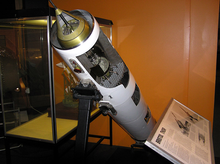
Basic description[]
The main missile is a long cylinder of magnesium frames and aluminium alloy skin with a prominent ogive nose cone at the front and some boat-tailing at the rear. Small aluminium-covered wooden cropped-delta wings are mounted midpoint, providing pitch and roll control by pivoting in unison or independently with additional steering provided by differential fuel feed to each of the ram jets. Two smaller rectangular fixed surfaces were mounted in-line with the main wings, almost at the rear of the missile.[6]
The boost engines are held together as a single assembly by a metal ring at the rear of the missile. Each motor has a small hook on the ring as well as similar one at the front holding it to the missile body. After firing, when the thrust of the rockets falls below the thrust of the now-lit ramjets, the boosters slide rearward until the front hook disengages from the missile body. The boosters are then free to rotate around their attachment to the metal ring, and are designed to rotate outward, away from the fuselage. In action, they fold open like the petals on a flower, greatly increasing drag and pulling the entire four-booster assembly away from the missile body.[15][16]
Small inlets on the roots of the stub wings holding the engines allow air into the missile body for two tasks. Two ram air turbines driving turbopumps generate hydraulic power for the wing control system, and a fuel pump that feeds the engines. Smaller inlet tubes provide ram air to pressurize the fuel tanks. Kerosene fuel is held in two large rubber bag tanks in bays either side of the wing bay where the wings are attached. Electrical power was provided by a molten salt battery ignited at launch.[6]
Although in tests the Bloodhound had executed direct hits on target bombers flying at 50,000 ft,[17] Mark II production models had proximity fused warheads designed to fire a hoop of metal rods and so destroy attacking aircraft without needing this degree of accuracy.[18]
Variants[]
Mk I[]
- Length : 7.7 m
- Launch Weight : 2,000 kg
- Range : 30 km
- Max. Speed : Mach 2.2
- Propulsion
- Main : 2× Bristol Thor ramjet engines
- Booster : 4× Gosling booster rockets

Mk II[]
- Length : 8.45 m
- Launch Weight :
- Range : 185 km
- Max. Speed : Mach 2.7
- Propulsion
- Main : 2× Thor ramjet engines (Improved)
- Booster : 4× Gosling booster rockets
The acceleration of the Mk. II can be gauged from the data on an information board at the Bristol Aeroplane Company Museum at Kemble Airfield, Kemble, Gloucestershire, where a complete Bloodhound can be seen. The Mark of Bloodhound this data refers to is not given but is presumably the Mark II since the top speed of the Mk. I is Mach 2.2:
"By the time the missile has just cleared the launcher it is doing 400 mph. By the time the missile is 25 feet from the launcher it has reached the speed of sound (around 720 mph). Three seconds after launch, as the four boost rockets fall away, it has reached Mach 2.5 which is roughly 1,800 mph"
Mk III[]
The planned Mk III (also known as RO 166) was a nuclear warhead equipped Mark II with a longer range (around 75-mile) achieved with improved Ramjet engine and bigger boosters. The project, one of several adaptations of existing British missiles to carry tactical nuclear devices, was cancelled in 1960. There is evidence that the intention was to "poison" the warheads of nuclear weapons carried by an attacking force via the neutron flux emitted by the warhead.[19]
Mk IV[]
This would have been a mobile version of Bloodhound.
Operators[]
 Australia
- Singapore
- Republic of Singapore Air Force
- 170 Squadron, Republic of Singapore Air Force (Mk II)
- Sweden
- Swedish Air Force
- RB-65 :Swedish military designation of Mk I
- RB-68 :Swedish military designation of Mk II
- Air force Wing F 8 At Barkaby had two Missile squadrons RB-68
- Air force Wing F 10 At Ängelholm had One Missile squadron RB-68
- Air force Wing F 12 At Kalmar had One Missile squadron RB-68
- Air force Wing F 13 At Norrköping had One Missile squadron RB-68
- Air force Wing F 17 At Ronneby had One Missile squadron RB-68
- Switzerland
- Swiss Air Force
- BL-64 : Swiss military designation
- United Kingdom
- Royal Air Force
- No. 25 Squadron RAF (Mk II)
- No. 33 Squadron RAF (Mk II)
- No. 41 Squadron RAF (Mk II)
- No. 62 Squadron RAF (Mk I)
- No. 65 Squadron RAF (Mk II)
- No. 85 Squadron RAF (Mk II)
- No. 94 Squadron RAF (Mk I)
- No. 112 Squadron RAF (Mk I) and (Mk II)
- No. 141 Squadron RAF (Mk I)
- No. 222 Squadron RAF (Mk I)
- No. 242 Squadron RAF (Mk I)
- No. 247 Squadron RAF (Mk I)
- No. 257 Squadron RAF (Mk I)
- No. 263 Squadron RAF (Mk I)
- No. 264 Squadron RAF (Mk I)
- No. 266 Squadron RAF (Mk I)
Preserved examples[]
![]() Australia
Australia
- Classic Jets Fighter Museum, Parafield Airport, Adelaide, South Australia
- Gate guardians at RAAF Base Darwin, Northern Territory
- RAAF Museum, Point Cook, Victoria
- Queensland Air Museum Caloundra Airport, Caloundra, Queensland[20]
![]() Singapore
Singapore
![]() Sweden
Sweden
- Ängelholms Flygmuseum. Ängelholm
![]() Switzerland
Switzerland
- Flieger Flab Museum. Dübendorf
![]() United Kingdom
United Kingdom
- Bristol Industrial Museum (Bristol Thor engine components)
- Imperial War Museum Duxford
- Muckleburgh Collection, Weybourne, Norfolk
- North East Aircraft Museum, Sunderland Airport
- RAF Abingdon, Abingdon, Oxfordshire
- RAF Air Defence Radar Museum, RAF Neatishead, Norwich, Norfolk
- Royal Air Force Museum Cosford
- Royal Air Force Museum London
See also[]
References[]
- Notes
- ↑ 1.0 1.1 "The Stage Plan." skomer.u-net.com. Retrieved: 14 May 2011.
- ↑ "Red Shoes." skomer.u-net.com. Retrieved: 14 May 2011.
- ↑ 3.0 3.1 3.2 "Bloodhound." skomer.u-net.com. Retrieved: 14 May 2011.
- ↑ 4.0 4.1 King 1959, p. 431.
- ↑ 5.0 5.1 King 1959, p. 434.
- ↑ 6.0 6.1 6.2 King 1959, p. 435.
- ↑ "Ferranti timeline, 1964." mosi.org.uk. Retrieved: 14 May 2011.
- ↑ "Bristol Blue Envoy long-range guided missile." skomer.u-net.com. Retrieved: 14 May 2011.
- ↑ "PRO document AIR 20/10625" (compares ranges of UK missile systems). skomer.u-net.com. Retrieved: 14 May 2011.
- ↑ Barrett, Dick. "The Radar Pages, Bloodhound: Life in the Old Dog." Royal Air Force Year Book 1990. Retrieved: 14 May 2011.
- ↑ "Export Sales Brochure: Bloodhound 21 Weapons System." braw.co.uk. Retrieved: 14 May 2011.
- ↑ "Obituary: Wing Commander F. W. Higginson, OBE, DFC, DFM, wartime fighter ace." The Times, 14 February 2003. Retrieved: 14 May 2011.
- ↑ Catford, Nick. "Rattlesden Mk. 1 Bloodhound Missile Site." subbrit.org.uk, 16 May 2008. Retrieved: 14 May 2011.
- ↑ "Bristol Bloodhound." wingweb.co. Retrieved: 14 May 2011.
- ↑ King 1959, p. 436.
- ↑ "Britain's Missiles (Image of Bloodhound test, with booster separation)". 28 August 1953. p. 242. http://www.flightglobal.com/pdfarchive/view/1953/1953%20-%201090.html.
- ↑ Bud 1999, p. 94.
- ↑ Cocroft and Thomas (Barnwell) 2003, p. 159.
- ↑ Bud 1999[page needed]
- ↑ http://qam.com.au/aircraft/bloodhound/bloodhound-04.htm
- Bibliography
- "Bloodhound: The SAGW System of the Royal Air Force." Flight International, 23 October 1959, pp. 431–438.
- Bud, Robert. Cold War, Hot Science: Applied Research in Britain's Defence Laboratories, 1945–1990. London: Science Museum, 2002, First edition 1999. ISBN 978-1-900747-47-9.
- Cocroft, Wayne and Roger J. C. Thomas. "The response — air defence". In Barnwell, P. S. Cold War Building for Nuclear Confrontation 1946–1989. Swindon, UK: English Heritage, 2003. ISBN 978-1-873592-81-6.
- Fitzsimons, Bernard, ed. The Illustrated Encyclopedia of 20th Century Weapons and Warfare. London: Phoebus, Volume 4, 1978, p. 389.
External links[]
| Wikimedia Commons has media related to Bristol Bloodhound. |
- Subterranea Britannica - Wattisham Mk. 2 Bloodhound Missile Site
- Bloodhound MKII - SAGW
- RB 68 Bloodhound Mk II (Swedish)
- Bloodhound Mk II
- Pathe newsreel footage of a Bloodhound test launch
| |||||||||||||||||||||||
The original article can be found at Bristol Bloodhound and the edit history here.