
A closeup of continuous tracks on a bulldozer
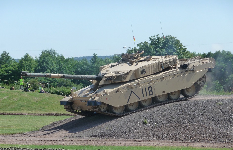
A British Army Challenger 1 tank

An agricultural tractor with rubber tracks
Continuous track, also called tank tread[1] or caterpillar track, is a system of vehicle propulsion in which a continuous band of treads is driven by two or more wheels. This band is typically made of modular steel plates in the case of military vehicles, or rubber reinforced with steel wires in the case of lighter agricultural or construction vehicles. The large surface area of the tracks distributes the weight of the vehicle better than steel or rubber tires on an equivalent vehicle, enabling a continuous tracked vehicle to traverse soft ground with less likelihood of becoming stuck due to sinking. The prominent treads of the metal plates are both hard-wearing and damage resistant, especially in comparison to rubber tires. The aggressive treads of the tracks provide good traction in soft surfaces but can damage paved surfaces. Special tracks that incorporate rubber pads can be installed for use on paved surfaces to prevent the damage that can be caused by all-metal tracks.
Continuous tracks can be traced back as far as 1770 and today are commonly used on a variety of vehicles including bulldozers, excavators, tanks, and tractors, but can be found on any vehicle used in an application that can benefit from the added traction, low ground pressure and durability inherent in continuous track propulsion systems.
History[]


Lombard Steam Log Hauler (Designed, patented 1901)

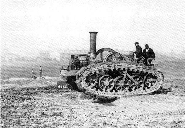
David Roberts tracked steam tractor c.1908


Hornsby tractor, 1909
Perhaps the oldest implementation of something resembling continuous tracks is to be found in theories of prehistoric erection of large stone monuments, when megaliths may have been slid atop rounded wooden logs. The logs were grooved near their ends to be held in alignment and rotation by belts out past the edge of the megalith and lubricated by some means, probably organic. The logs are carried from the back of the procession to the front in an endless chain, like continuous track. The system is a precursor to development of the axle, which keeps a rotating cylinder fixed relative to its cargo.
In modern times, continuous track propulsion systems can be traced back to a crude continuous track system designed in the 1770s by Richard Lovell Edgeworth. Polish mathematician and inventor Józef Maria Hoene-Wroński conceived of the idea in the 1830s.[2] The British polymath Sir George Cayley patented a continuous track, which he called a "universal railway".[3] In 1837, a Russian inventor Dmitry Zagryazhsky designed a "carriage with mobile tracks" which he patented the same year, but due to a lack of funds he was unable to build a working prototype, and his patent was voided in 1839.
Although not a continuous track in the form encountered today, a Dreadnaught Wheel or "endless railway wheel" was patented by the British Engineer James Boydell in 1846. In Boydell's design, a series of flat feet are attached to the periphery of the wheel, spreading the weight.[4] A number of horse-drawn wagons, carts and gun carriages were successfully deployed in the Crimean War, waged between October 1853 and February 1856, the Royal Arsenal at Woolwich manufacturing dreadnaught wheels. A letter of recommendation was signed by Sir William Codrington, the General commanding the troops at Sebastapol.[5][6]
Boydell patented improvements to his wheel in 1854 (No. 431) - the year his dreadnaught wheel was first applied to a steam engine - and 1858 (No. 356), the latter an impracticable palliative measure involving the lifting one or other of the driving wheels to facilitate turning.
A number of manufacturers including Richard Bach, Richard Garrett & Sons, Charles Burrell & Sons and Clayton & Shuttleworth applied the Boydell patent under licence. The British military were interested in Boydell's invention from an early date. One of the objectives was to transport Mallet's Mortar, a giant 36" weapon which was under development but, by the end of the Crimean war, the mortar was not ready for service. A detailed report of the tests on steam traction, carried out by a select Committee of the Board of Ordnance, was published[7] in June 1856, by which date the Crimean War was over, consequently the mortar and its transportation became irrelevant. In those tests, a Garrett engine was put through its paces on Plumstead Common. The Garrett engine featured in the Lord Mayor's show in London, and in the following month that engine was shipped to Australia. A steam tractor employing dreadnaught wheels was built at Bach's Birmingham works, and was used between 1856 and 1858 for ploughing in Thetford; and the first generation of Burrell/Boydell engines was built at the St. Nicholas works in 1856, again, after the close of the Crimean war.[8] Between late 1856 and 1862 Burrell manufactured not less than a score of engines fitted with dreadnaught wheels. And in April 1858, "The Engineer" gave a brief description of a Clayton & Shuttleworth engine fitted with dreadnaught wheels, which was supplied not to the Western Allies, but to the Russian Government for heavy artillery haulage in the Crimea, in the post-war period.[9] Steam tractors fitted with Dreadnaught wheels had a number of shortcomings and, notwithstanding the creations of the late 1850s, were never used extensively.[6][10]
In August 1858, more than two years after the end of the Crimean War, John Fowler (agricultural engineer) filed British Patent No. 1948 on another form of "Endless Railway". In his illustration of the invention, Fowler used a pair of wheels of equal diameter on each side of his vehicle, around which pair of toothed wheels ran a 'track' of eight jointed segments, with a smaller jockey/drive wheel between each pair of wheels, to support the 'track'. Comprising only eight sections, the 'track' sections are essentially 'longitudinal', as in Boydell's initial design.[11] Fowler's arrangement is a precursor to the multi-section caterpillar track in which a relatively large number of short 'transverse' treads are used, as proposed by Sir George Caley in 1825,[12] rather than a small number of relatively long 'longitudinal' treads.
Further to Fowler's patent of 1858, in 1877, a Russian, Fyodor Blinov, created a tracked vehicle called "wagon moved on endless rails" (caterpillars).[13] It lacked self-propulsion and was pulled by horses. Blinov received a patent for his "wagon" in 1878. From 1881 to 1888 he developed a steam-powered caterpillar-tractor. This self-propelled crawler was successfully tested and featured at a farmers' exhibition in 1896.[13]
Steam traction engines were used at the end of the 19th Century in the Boer Wars. But neither dreadnaught wheels nor continuous tracks were used, rather "roll-out" wooden plank roads were thrown under the wheels as required.[14]
In short, whilst the development of the continuous track engaged the attention of a number of inventors in the 18th and 19th centuries, the general use and exploitation of the continuous track belonged to the 20th Century.
A little known American inventor, Henery T. Stith, developed a continuous track prototype which was, in multiple forms, patented in 1873, 1880, and 1900. The last was for the application of the track to a prototype off-road bicycle built for his son.[1] The 1900 prototype is retained by his surviving family.
An effective continuous track was invented and implemented by Alvin Orlando Lombard for the Lombard Steam Log Hauler. He was granted a patent in 1901 and built the first steam-powered log hauler at the Waterville Iron Works in Waterville, Maine, the same year. In all, 83 Lombard steam log haulers are known to have been built up to 1917, when production switched entirely to internal combustion engine powered machines, ending with a Fairbanks diesel powered unit in 1934. Undoubtedly, Alvin Lombard was the first commercial manufacturer of the tractor crawler. At least one of Lombard's steam-powered machines apparently remains in working order.[15] A gasoline-powered Lombard hauler is on display at the Maine State Museum in Augusta.
In addition, there may have been up to twice as many Phoenix Centipeed versions of the steam log hauler built under license from Lombard, with vertical instead of horizontal cylinders. In 1903, the founder of Holt Manufacturing, Benjamin Holt, paid Lombard $60,000 for the right to produce vehicles under his patent. There seems to have been an agreement made after Lombard moved to California, but when previous track patents were studied, discrepancies arose concerning how this matter was resolved.
At about the same time a British agricultural company, Hornsby in Grantham, developed a continuous track which was patented in 1905.[16] The design differed from modern tracks in that it flexed in only one direction, with the effect that the links locked together to form a solid rail on which the road wheels ran. Hornsby's tracked vehicles were given trials as artillery tractors by the British Army on several occasions between 1905 and 1910, but not adopted. The patent was purchased by Holt. The Hornsby tractors featured a track-steer clutch arrangement, which is the basis of the modern crawler operation, and some say an observing British soldier quipped that it crawled like a caterpillar. The word was shrewdly trademarked and defended by Holt.
American James B. Hill, working in Bowling Green, Wood County, Ohio, patented what he termed "apron traction"[17] on September 24, 1907.

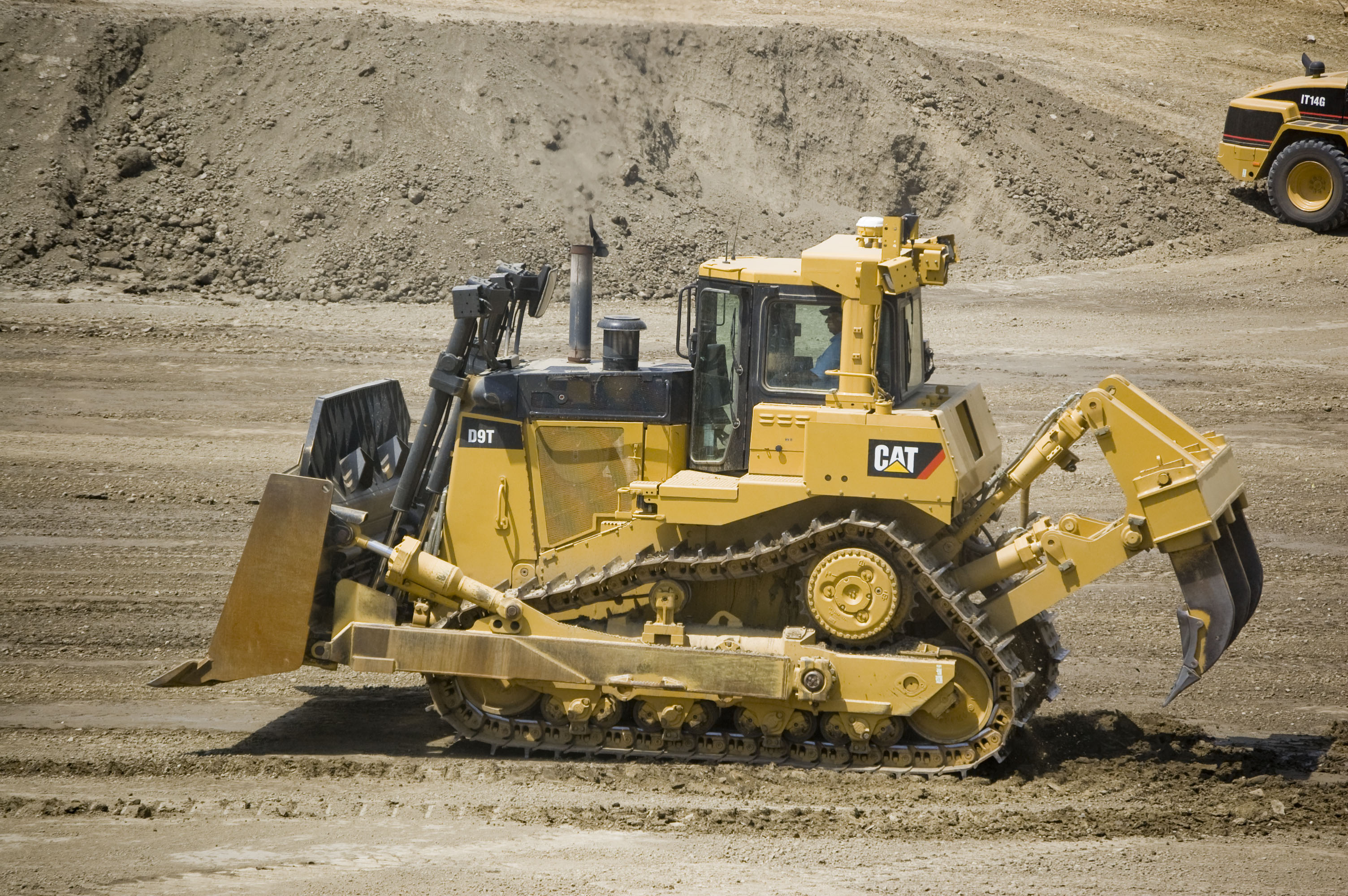
A modern Caterpillar Inc. D9T bulldozer
Caterpillar Tractor Company began in 1925 from a merger of the Holt Manufacturing Company and the C. L. Best Tractor Company; an early successful manufacturer of crawler tractors. Caterpillar brand continuous tracks have since revolutionized construction vehicles and land warfare. Track systems have been developed and improved during their use on fighting vehicles. During World War I Holt tractors were used by the British and Austro-Hungarian armies to tow heavy artillery and stimulated the development of tanks in several countries. The first tanks to go into action, the Mark I, built by Great Britain, were designed from scratch and were inspired by but not directly based on the Holt. The slightly later French and German tanks were built on modified Holt running gear.
A concept vehicle called the Hyanide proposes a continuous track drive motorcycle. It involves a steerable continuous track to enable the vehicle to corner.[18]
The Canadian company BPG Werks has developed a dual tracked recreational vehicle called the DTV Shredder. This gasoline-powered vehicle consists of two caterpillar tracks steered by activating a dual CVT connected to the rider deck. As the rider leans the deck side to side, the speed of the tracks change allowing for differential steering.[19][20]
Patent history[]
A long line of patents disputes who the "originator" was of continuous tracks. There were a number of designs that attempted to achieve a track laying mechanism, although these designs do not generally resemble modern tracked vehicles.[21][22][23]
Blinov[]
The draft of Blinov's steam-powered continuous track tractor
In 1877 Russian inventor Fyodor Abramovich Blinov created tracked vehicle called "wagon moved on endless rails" (caterpillars).[13] It lacked self-propelling and was horse-drawn. Blinov got a patent for his "wagon" the next year. Later, in 1881-1888 he created a steam-powered caterpillar-tractor. This self-propelled crawler was successfully tested and showed at a farmers' exhibition in 1896.[13]
Dinsmoor[]
According to Scientific American, it was Charles Dinsmoor of Warren, Pennsylvania that invented a "vehicle" that was of endless tracks. The article gives a detailed description of the endless tracks and the illustration looks much like today's tracked vehicles.[24] The invention has been patented as No. 351,749 on November 2, 1886.[25][26]
Lombard[]
Alvin O. Lombard of Waterville, Maine was issued a patent in 1901 for the Lombard Steam Log Hauler that resembles a regular railroad steam locomotive with sled steerage on front and crawlers in rear for hauling logs in the Northeastern United States and Canada.[citation needed] The haulers allowed pulp to be taken to rivers in the winter. Prior to then, horses could be used only until snow depths made hauling impossible. Lombard began commercial production which lasted until around 1917 when focus switched entirely to gasoline powered machines. A gasoline powered hauler is on display at the Maine State Museum in Augusta, Maine.
Hornsby/Holt/Phoenix[]


A Model of the Hornsby tractor
After Lombard began operations, Hornsby in England manufactured at least two full length "track steer" machines, and their patent was later purchased by Holt in 1913, allowing Holt to claim to be the "inventor" of the crawler tractor.[27] Since the "tank" was a British concept it is more likely the Hornsby, which had been built and unsuccessfully pitched to their military, was the inspiration.
In a patent dispute involving rival crawler builder Best, testimony was brought in from people including Lombard, that Holt had inspected a Lombard log hauler shipped out to a western state by people who would later build the Phoenix log hauler in Eau Claire, Wisconsin, under license from Lombard.[citation needed] The Phoenix Centipeed typically had a fancier wood cab, steering wheel tipped forward at a 45 degree angle and vertical instead of horizontal cylinders.
Linn[]
In the meantime a gasoline powered motor home was built by Lombard for Holman Harry (Flannery) Linn of Old Town, Maine to pull the equipment wagon of his dog & pony show, resembling a trolley car only with wheels in front and Lombard crawlers in rear. Linn had experimented with gasoline and steam powered vehicles and six wheel drive before this, and at some point entered Lombard's employment as a demonstrator, mechanic and sales agent. This resulted in a question of proprietorship of patent rights after a single rear tracked gasoline powered road engine of tricycle arrangement was built to replace the larger motor home in 1909 on account of problems with the old picturesque wooden bridges. This dispute resulted in Linn departing Maine and relocating to Morris, New York, to build an improved, contour following flexible lag tread or crawler with independent suspension of halftrack type, gasoline and later diesel powered. Although several were delivered for military use between 1917 and 1946, Linn never received any large military orders. Most of the production between 1917 and 1952, approximately 2500 units, was sold directly to highway departments and contractors. Steel tracks and payload capacity allowed these machines to work in terrain that would typically cause the poorer quality rubber tires that existed before the mid-1930s to spin uselessly, or shred completely.[citation needed]
Linn was a pioneer in snow removal before the practice was embraced in rural areas, with a nine foot steel v-plow and sixteen foot adjustable leveling wings on either side. Once the highway system became paved, snowplowing could be done by four wheel drive trucks equipped by improving tire designs, and the Linn became an off highway vehicle, for logging, mining, dam construction, arctic exploration, etc.[citation needed]
Sloan[]
Once steel cleats became unpopular on paved roads, in 1938 a limited experiment began to bridge the gap between truck and tractor, a "convertible vehicle" patented by Phillip Sloan, the C5 Catruk, suffered design flaws and limited production before it was finally abandoned.[citation needed]
Engineering[]
Construction and operation[]


.png)
Diagram of tracked suspension.(1=rear drive wheel (rear wheel drive), 2=track, 3=return rollers, 4=front drive wheel (front wheel drive), 5=road wheels, 6=idler)


A sprocket wheel on a tank
Modern tracks are built from modular chain links which together compose a closed chain. The links are jointed by a hinge, which allows the track to be flexible and wrap around a set of wheels to make an endless loop. The chain links are often broad, and made of manganese alloy steel for high strength, hardness, and abrasion resistance.[28]
Track construction and assembly is dictated by the application. Military vehicles use a track shoe that is integral to the structure of the chain in order to reduce track weight. Reduced weight allows the vehicle to move faster and decreases overall vehicle weight to ease transportation. Since track weight is completely unsprung, reducing it improves suspension performance at speeds where the track's momentum is significant. In contrast, agricultural and construction vehicles opt for a track with shoes that attach to the chain with bolts and do not form part of the chain's structure. This allows track shoes to break without compromising the ability of the vehicle to move and decrease productivity but increases the overall weight of the track and vehicle. Extra weight is an advantage when optimizing for traction and power over speed and mobility.
The vehicle's weight is transferred to the bottom length of track by a number of road wheels, or sets of wheels called bogies. Road wheels are typically mounted on some form of suspension to cushion the ride over rough ground. Suspension design in military vehicles is a major area of development; the very early designs were often completely unsprung. Later-developed road wheel suspension offered only a few inches of travel using springs, whereas modern hydro-pneumatic systems allow several feet of travel and include shock absorbers. Torsion-bar suspension has become the most common type of military vehicle suspension. Construction vehicles have smaller road wheels that are designed primarily to prevent track derailment and they are normally contained in a single bogie that includes the Idler-wheel and sometimes the sprocket.
Transfer of power to the track is accomplished by a drive wheel, or drive sprocket, driven by the motor and engaging with holes in the track links or with pegs on them to drive the track. In military vehicles, the drive wheel is typically mounted well above the contact area on the ground, allowing it to be fixed in position. In agricultural crawlers it is normally incorporated as part of the bogie. Placing suspension on the sprocket is possible, but is mechanically more complicated. A non-powered wheel, an idler, is placed at the opposite end of the track, primarily to tension the track, since loose track could be easily thrown (slipped) off the wheels. To prevent throwing, the inner surface of the track links usually have vertical guide horns engaging grooves, or gaps between the doubled road and idler/sprocket wheels. In military vehicles with a rear sprocket, the idler wheel is placed higher than the road wheels to allow it to climb over obstacles. Some track arrangements use return rollers to keep the top of the track running straight between the drive sprocket and idler. Others, called slack track, allow the track to droop and run along the tops of large road wheels. This was a feature of the Christie suspension, leading to occasional misidentification of other slack track-equipped vehicles.
Overlapping road wheels[]


Overlapped and interleaved road wheels of a German Tiger I heavy tank
Many World War II German military vehicles, including all vehicles originally designed to be half-tracks and all later tank designs (after the Panzer IV), had slack-track systems, usually driven by a front-located drive sprocket, the track returning along the tops of a design of overlapping and sometimes interleaved large diameter road wheels, as on the suspension systems of the Tiger I and Panther tanks, generically known by the term Schachtellaufwerk in German. There were suspensions with one (sometimes double) wheel per axle, alternately supporting the inner and outer side of the track, and interleaved suspensions with two or three road wheels per axle, distributing the load over the track.[29] The choice of overlapping/interleaved road wheels allowed the use of slightly more torsion bar suspension members, allowing any German tracked military vehicle with such a setup to have a noticeably smoother ride over challenging terrain, leading to reduced wear and more accurate fire. As a tracked vehicle moves, the load of each wheel moves over the track, pushing down and forward that part of the earth, snow, etc. under it, similarly to a wheeled vehicle but to a lesser extent because the tread helps distribute the load. Apparently, on some surfaces, this consumes enough energy to slow the vehicle down significantly, so overlapped and interleaved wheels improve performance (including fuel consumption) by loading the track more evenly. It also must have extended the life of the tracks and possibly of the wheels. The wheels also better protect the vehicle from enemy fire, and mobility when some wheels are missing is improved. But this complicated approach has not been used since World War II ended. This may be related more to maintenance than to original cost. Mud and ice collect between the overlapping areas of the road wheels, freezing solid in cold weather conditions, often immobilizing vehicles equipped with such Schachtellaufwerk track suspension systems. The torsion bars and bearings may stay dry and clean, but the wheels and tread work in mud, sand, rocks, snow and so on. In addition, the outer wheels (up to 9 of them, some double) had to be removed to access the inner ones. In WW II, vehicles typically had to be maintained a few months before being destroyed or captured, but in peace time vehicles must train several crews, over a period of decades.
Advantages[]


A Russian tracked vehicle designed to operate on snow and swamps
Tracked vehicles have better mobility than pneumatic tyres over rough terrain. They smooth out the bumps, glide over small obstacles and are capable of crossing trenches or breaks in the terrain. Riding in a fast tracked vehicle feels like riding in a boat over heavy swells. Tracks are tougher than tyres since they cannot be punctured or torn. Tracks are much less likely to get stuck in soft ground, mud, or snow since they distribute the weight of the vehicle over a larger contact area, decreasing its ground pressure. In addition, the larger contact area, coupled with the cleats, or grousers, on the track shoes, allows vastly superior traction that results in a much better ability to push or pull large loads where wheeled vehicles would dig in. Bulldozers, which are most often tracked, use this attribute to rescue other vehicles, (such as wheel loaders) which have become stuck in, or sunk into, the ground. Tracks can also give higher maneuverability, as some tracked vehicle can turn in place without forward or backward movement by driving the tracks in opposite directions. In addition, should a track be broken, assuming the correct tools are available, it can be repaired without the need for special facilities; something which is crucial in a combat situation.
The seventy-ton M1 Abrams tank has an average ground pressure of just over 15 psi (100 kPa). Since tire air pressure is approximately equal to average ground pressure, a typical car will have an average ground pressure of 28 psi (190 kPa) to 33 psi (230 kPa).
Disadvantages[]


Tracked vehicles may be put on semitrailers or railway cars for long-distance hauling.

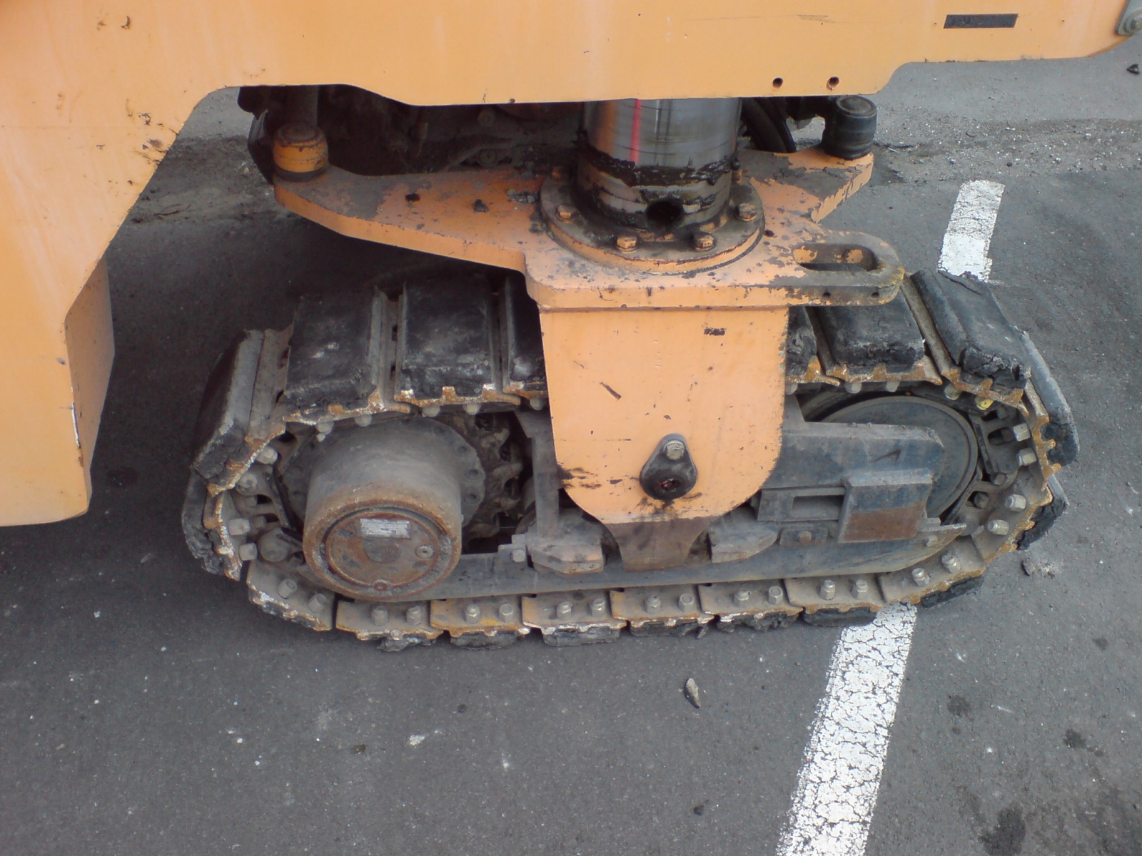
Small tracks on a roadworks machine, note the rubber pads to reduce wear on the carriageway.
The disadvantages of tracks are lower top speed, much greater mechanical complexity, shorter life and the damage that their all-steel versions cause to what passes beneath them. They are perceived/misconceived to severely damage hard terrain like asphalt pavement, but, actually, often have significantly lower ground pressures than equivalent or lighter wheeled vehicles. However, they often cause damage to less firm terrain such as lawns, gravel roads, and farm fields, as the sharp edges of the track easily rout the turf. Accordingly, vehicle laws and local ordinaces often require rubberised tracks or track pads. A compromise between all-steel and all-rubber tracks exists: attaching rubber pads to individual track links ensures that continuous track vehicles can travel more smoothly, quickly, and quietly on paved surfaces. While these pads slightly reduce a vehicle's cross-country traction, in theory they prevent damage to any pavement.
Additionally, the loss of a single segment in a track immobilizes the entire vehicle, which can be a disadvantage in situations where high reliability is important. Tracks can also ride off their guide wheels, idlers or sprockets, which can cause them to jam in an overly tight position or to come completely off the guide system (this is called a 'thrown' track). Jammed tracks may become so tight that the track may need to be broken before a repair is possible, which requires either explosives or special tools. Multi-wheeled vehicles, for example, 8 X 8 military vehicles, may often continue driving even after the loss of one or more non-sequential wheels, depending on the base wheel pattern and drive train.
Many manufacturers provide rubber tracks instead of steel, especially for agricultural applications. Rather than a track made of linked steel plates, a reinforced rubber belt with chevron treads is used. In comparison to steel tracks, rubber tracks are lighter, make less noise, create less maximal ground pressure and do not damage paved roads. The disadvantage is that they are not as solid as steel tracks. Previous belt-like systems, such as those used for half-tracks in World War II, were not as strong, and during military actions were easily damaged. The first rubber track was invented and constructed by Adolphe Kégresse and patented in 1913; rubber tracks are often called Kégresse tracks.
Prolonged use places enormous strain on the drive transmission and the mechanics of the tracks, which must be overhauled or replaced regularly. It is common to see tracked vehicles such as bulldozers or tanks transported long distances by a wheeled carrier such as a tank transporter or train, though technological advances have made this practice less common among tracked military vehicles than it once was.
Non-metal tread patterns[]
There are different varieties of non-metal core tracks that are designed for very different applications.
Aggressive Tread Pattern[]
Aggressive tread NMC tracks have a more traditional lug style. They produce more pushing power and more tractive effort than their anti-vibration counterpart. Pros: -Greatly improves traction in loose ground or wet, muddy or otherwise challenging terrain. -Designed to be rugged enough to handle asphalt and other tough debris on job sites. Cons: -Increased tractive power means that these have a higher level of ground disturbance than anti-vibration NMC tracks. -The operator will experience greater vibration in the machine. Bottom Line: This track type is best suited for work sites that have a lot of loose debris or material on the ground. This rugged track pattern also is well suited to lend much needed tractive support in muddy or unstable terrain.
Anti-Vibration Tread Pattern[]
The anti-vibration track is generally what is on your machine as the OEM component. This track has lower ground pressure than the Aggressive tread NMC tracks. Pros: -Allows machine to tread lighter, achieving less ground disturbance. -Very comfortable, vibration reduced ride for operator. Cons: -Less pushing power in the machine in comparison to the aggressive pattern NMC tracks. Bottom Line: This track type is best designed for applications such as landscaping work. You’ll have less rework and repair because of the reduced ground disturbance from this track type. Anti-vibration tracks are best suited for turf or other compact terrain that is mostly free of debris or loose materials. [30]
"Live" and "Dead" track[]
Tracks may be broadly categorized as "live" or "dead" track. "Dead" track is a simple design in which each track plate is connected to the rest with hinge-type pins. These dead tracks will lie flat if placed on the ground; the drive sprocket pulls the track around the wheels with no assistance from the track itself. "Live" track is slightly more complex, with each link connected to the next by a bushing which causes the track to bend slightly inward. A length of live track left on the ground will curl upward slightly at each end. Although the drive sprocket must still pull the track around the wheels, the track itself tends to bend inward, slightly assisting the sprocket and somewhat conforming to the wheels.
Current manufacturers[]
The pioneer manufacturers have been replaced mostly by large tractor companies such as Liebherr Group,[31] John Deere, Yanmar, New Holland, Kubota,[32] Case, Caterpillar Inc., CLAAS.[33] Also, there are some crawler tractor companies specialising in niche markets. Examples are Otter Mfg. Co. and Struck Corporation.[34]
Big Russian off-road territories forces many to develop and keep tracked transporters for the country. ZZGT,[35] Vityaz[36] and some other producers cover the needs of oil&gas, geophysics, forestry companies and governmental services.
See also[]
| Wikimedia Commons has media related to Continuous tracks. |
- Excavator
- Half-track
- Kégresse track
- Pedrail wheel
- Screw-propelled vehicle
- Snowcat
- Snowmobile
References[]
- ↑ 1.0 1.1 "The Tank Tread Was His Baby". 1944. p. 63. http://books.google.com/books?id=mCYDAAAAMBAJ&pg=PA63. Retrieved 2011-08-24.
- ↑ "Josef-Maria Hoëné de Wronski". http://www-history.mcs.st-andrews.ac.uk/Biographies/Wronski.html. Retrieved 2009-05-30.
- ↑ "Sir George Cayley's patent universal railway". 1826-01-28. pp. 225–227. http://books.google.com/books?id=_roAAAAAMAAJ&pg=PA225.
- ↑ "Burrell's traction engine with Boydell's endless railway". Grace's Guide. 1857. http://www.gracesguide.co.uk/images/8/86/Im1862EnV13-p284.jpg. Retrieved 2013-09-30.
- ↑ Lane, Michael R. (1994). The story of the St. Nicholas Works: A History of Charles Burrell and Sons. London: Unicorn Press. ISBN 978-0906290071.
- ↑ 6.0 6.1 "Boydell Artillery Wheel". http://www.users.waitrose.com/~brbeamond/Boydell%20Artillery%20Wheel.pdf. Retrieved 2013-09-30.
- ↑ {The Mark Lane Express, June 30, 1856}
- ↑ "Boydell's traction engine". Science & Society: Picture library. 1857. http://www.scienceandsociety.co.uk/results.asp?image=10318750. Retrieved 2013-09-30.
- ↑ {op. cit. Michael R. Lane 1994}
- ↑ "Charles Burrell & Sons Limited". University of Reading. UK. https://www.reading.ac.uk/web/FILES/merl/Microsoft_Word_-_Burrell_Catalogue.pdf. Retrieved 2013-09-30.
- ↑ "Burrell-Boydell Tractor". http://www.users.waitrose.com/~brbeamond/Burrell-Boydell%20Tractor.pdf. Retrieved 2013-09-30.
- ↑ Caley, Georg (1825). "Patent No. 5260 A New Locomotive Apparatus". http://www.users.waitrose.com/~brbeamond/Sir%20George%20Caley's%20Continuous%20Track.pdf. Retrieved 2013-09-30.
- ↑ 13.0 13.1 13.2 13.3 "The inventor of the tractor" (in Russian). http://ricolor.org/history/eng/prm/blinov/. Retrieved 2011-08-24. Cite error: Invalid
<ref>tag; name "blinov" defined multiple times with different content - ↑ {The Implement and Machinery Review January 2, 1901}
- ↑ "Lombard Log Hauler and Model T Snowmobile Show Route 175 Thornton, NH". http://www.allroutes.to/modeltandlombard/. Retrieved 2011-08-24.
- ↑ British Patent No. 16,345 (1904)
- ↑ U.S. Patent 0,866,647
- ↑ Dawn Stove (1 Aug 2006). "Your very own personal tank". http://www.popsci.com/popsci/whatsnew/5fa21e6759a4c010vgnvcm1000004eecbccdrcrd.html. Retrieved 2011-08-24.
- ↑ "DTV Shredder: an all-terrain powered skateboard for the military". http://www.geek.com/articles/news/dtv-shredder-an-all-terrain-powered-skateboard-for-the-military-20100913/. Retrieved 3 December 2011.
- ↑ "DTV Shredder stands up for off-roading". http://www.gizmag.com/dtv-shredder-tracked-vehicle/16668/. Retrieved 3 December 2011.
- ↑ US patent 69987, James K Glen, "Improvement in Motive Power", issued 1867-10-22
- ↑ US patent 373887, William Fender, "Wheel With Endless Rail", issued 1887-11-29
- ↑ US patent 433488, Goldsbury Harden Pond, "Traction Engine", issued 1890-08-05
- ↑ Scientific American, December 18, 1886, Vol. LV, No. 25
- ↑ Kane, Joseph Nathan, Famous First Facts, H. W. Wilson Company (1950), p. 47
- ↑ US patent 351749, Charles Dinsmoor, "Vehicle", issued 1886-11-02 A design for a tracked vehicle.
- ↑ "Caterpillar Tractor Co. List of Deals". Lehman Brothers Collection. President and Fellows of Harvard College. 2010. Archived from the original on 2010-11-06. http://www.webcitation.org/5u2jB9nzf. Retrieved 2010-11-06. "In 1925 Holt and C.W. Best's company merged to form the Caterpillar Tractor Company."
- ↑ "Austenitic Manganese Steels". http://www.keytometals.com/page.aspx?ID=CheckArticle&site=kts&NM=69. Retrieved 2011-08-24.
- ↑ Peter Chamberlain and Hilary Doyle ,Encyclopedia of German Tanks of World War II, 1999
- ↑ Which MTL Non-Metal Core Rubber Track is Right for your Business? National 1 Rubber Track
- ↑ "Official website". Liebherr. http://liebherr.com/. Retrieved 2013-05-03.
- ↑ "Kubota crawler tractor". Kubota.com. 14 July 2008. http://www.kubota.com/f/aboutkubota/prl67.cfm. Retrieved 2013-05-03.
- ↑ "Search results for Used Tracked tractors". Mascus.co.uk. http://www.mascus.co.uk/Agriculture/Used-Tracked-tractors. Retrieved 2013-05-03.
- ↑ Otter & Struck manufacturing niche crawler tractors[dead link]
- ↑ [1]
- ↑ [2]
The original article can be found at Continuous track and the edit history here.