
Amelia Earhart's Lockheed Model 10 Electra with the circular RDF aerial visible above the cockpit
A radio direction finder (RDF) is a device for finding the direction, or bearing, to a radio source. The act of measuring the direction is known as radio direction finding or sometimes simply direction finding (DF). Using two or more measurements from different locations, the location of an unknown transmitter can be determined; alternately, using two or more measurements of known transmitters, the location of a vehicle can be determined. RDF is widely used as a radio navigation system, especially with boats and aircraft.
RDF systems can be used with any radio source, although the size of the receiver antennas are a function of the wavelength of the signal; very long wavelengths (low frequencies) require very large antennas, and are generally used only on ground-based systems. These wavelengths are nevertheless very useful for marine navigation as they can travel very long distances and "over the horizon", which is valuable for ships when the line-of-sight may be only a few tens of kilometres. For aerial use, where the horizon may extend to hundreds of kilometres, higher frequencies can be used, allowing the use of much smaller antennas. An automatic direction finder, often tuned to commercial AM radio broadcasters, is a feature of almost all modern aircraft.
For the military, RDF systems are a key component of signals intelligence systems and methodologies. The ability to locate the position of an enemy broadcaster has been invaluable since World War I, and play a key role in World War II's Battle of the Atlantic. It is estimated that the UK's advanced "huff-duff" systems were directly or indirectly responsible for 24% of all U-Boats sunk during the war. Modern systems often used phased array antennas to allow rapid beam forming for highly accurate results. These are generally integrated into a wider electronic warfare suite.
Several distinct generations of RDF systems have been used over time, following the development of new electronics. Early systems used mechanically rotated antennas that compared signal strengths in different directions, and several electronic versions of the same concept followed. Modern systems use the comparison of phase or doppler techniques which are generally simpler to automate. Modern pseudo-Doppler direction finder systems consist of a number of small antennas fixed to a circular card, with all of the processing occurring in software.
Early British radar sets were also referred to as RDF, which was a deception tactic. However, the terminology was not inaccurate; the Chain Home systems used separate omni-directional broadcasters and large RDF receivers to determine the location of the targets.[1]
History[]
Early mechanical systems[]

W.G. Wade of the National Bureau of Standards uses a large multi-loop antenna to perform RDF in this 1919 photo. This is a fairly small unit for the era.
The earliest experiments in RDF were carried out in 1888 when Heinrich Hertz discovered the directionality of an open loop of wire used as an antenna. When the antenna was aligned so it pointed at the signal it produced maximum gain, and produced zero signal when face on. This meant there was always an ambiguity in the location of the signal, it would produce the same output if the signal was in front or back of the antenna. Later experimenters also used dipole antennas, which worked in the opposite sense, reaching maximum gain at right angles and zero when aligned. RDF systems using mechanically swung loop or dipole antennas were common by the turn of the 20th century. Prominent examples were patented by John Stone Stone in 1902 (U.S. Patent 716,134) and Lee de Forest in 1904 (U.S. Patent 771,819), among many other examples.
By the early 1900s, many experimenters were looking for ways to use this concept for locating the position of a transmitter. Early radio systems generally used medium wave and longwave signals. Longwave in particular had good long-distance transmission characteristics due to their limited interaction with the ground, and thereby provided excellent great circle route ground wave propagation that pointed directly to the transmitter. Methods of performing RDF on longwave signals was a major area of research during the 1900s and 1910s.[2]
Antennas are generally sensitive to signals only when they have a length that is a significant portion of the wavelength, or larger. Most antennas are at least ¼ of the wavelength, more commonly ½ - the half-wave dipole is a very common design. For longwave use, this resulted in loop antennas tens of feet on a side, often with more than one loop connected together to improve the signal. Another solution to this problem was developed by the Marconi company in 1905. This consisted of a number of horizontal wires or rods arranged to point outward from a common center point. A movable switch could connect opposite pairs of these wires to form a dipole, and by rotating the switch the operator could hunt for the strongest signal.[3] The US Navy overcame this problem, to a point, by mounting antennas on ships and sailing in circles.[4] Such systems were unwieldily and impractical for many uses.[5]
Bellini-Tosi[]

This Royal Navy model is typical of B-T goniometers. The two sets of "field coils" and the rotating "sense coil" are visible.
A key improvement in the RDF concept was introduced by Ettore Bellini and Alessandro Tosi in 1909 (U.S. Patent 943,960). Their system used two such antennas, typically triangular loops, arranged at right angles. The signals from the antennas were sent into coils wrapped around a wooden frame about the size of a pop can, where the signals were re-created in the area between the coils. A separate loop antenna located in this area could then be used to hunt for the direction, without moving the main antennas. This made RDF so much more practical that it was soon being used for navigation on a wide scale, often as the first form of aerial navigation available, with ground stations homing in on the aircraft's radio set. Bellini-Tosi direction finders were widespread from the 1920s into the 1950s.
Early RDF systems were useful largely for long wave signals. These signals are able to travel very long distances, which made them useful for long-range navigation. However, when the same technique was being applied to higher frequencies, unexpected difficulties arose due to the reflection of high frequency signals from the ionosphere. The RDF station might now receive the same signal from two or more locations, especially during the day, which caused serious problems trying to determine the location. This led to the 1919 introduction of the Adcock antenna (UK Patent 130,490), which consisted of four separate monopole antennas instead of two loops, eliminating the horizontal components and thus filtering out the sky waves being reflected down from the ionosphere. Adcock antennas were widely used with Bellini-Tosi detectors from the 1920s on.
The US Army Air Corps in 1931 tested a primitive radio compass that used commercial stations as the beacon.[6]
Huff-duff[]


FH4 "Huff-duff" equipment on the museum ship HMS Belfast
A major improvement in the RDF technique was introduced by Robert Watson-Watt as part of his experiments to locate lightning strikes as a method to indicate the direction of thunderstorms to sailors and airmen. He had long worked with conventional RDF systems, but these were difficult to use with the fleeting signals from the lightning. He had early on suggested the use of an oscilloscope to display these near instantly, but was unable to find one while working at the Met Office. When the office was moved, his new location at a radio research station provided him with both an Adcock antenna and a suitable oscilloscope, and he presented his new system in 1926.
In spite of the system being presented publicly, and its measurements widely reported in the UK, its impact on the art of RDF seems to be strangely subdued. Development was limited until the mid-1930s, when the various British forces began widespread development and deployment of these "high-frequency direction finding", or "huff-duff" systems. To avoid RDF, the Germans had developed a method of broadcasting short messages under 30 seconds, less than the 60 seconds that a trained Bellini-Tosi operator would need to determine the direction. However, this was useless against huff-duff systems, which located the signal with reasonable accuracy in seconds. The Germans did not become aware of this problem until the middle of the war, and did not take any serious steps to address it until 1944. By that time huff-duff had helped in about one-quarter of all successful attacks on the U-boat fleet.
Post-war systems[]
Several developments in electronics during and after the war led to greatly improved methods of comparing the phase of signals. In addition, the phase-locked loop (PLL) allowed for easy tuning in of signals, which wouldn't drift. Improved vacuum tubes and the introduction of the transistor allowed much higher frequencies to be used economically, with led to widespread use of VHF and UHF signals. All of these changes led to new methods of RDF, and much more widespread use.
In particular, the ability to compare the phase of signals led to phase-comparison RDF, which is perhaps the most widely used technique today. In this system the loop antenna is replaced with a single square-shaped ferrite core, with loops wound around two perpendicular sides. Signals from the loops are sent into a phase comparison circuit, who's output phase directly indicates the direction of the signal. By sending this to any manner of display, and locking the signal using PLL, the direction to the broadcaster can be continuously displayed. Operation consists solely of tuning in the station, and is so automatic that these systems are normally referred to as automatic direction finder.
Other systems have been developed where more accuracy is required. pseudo-doppler radio direction finder systems use a series of small dipole antennas arranged in a ring and use electronic switching to rapidly select pairs of dipoles to feed into the receiver. The resulting signal is processed and produces an audio tone, whose frequency is dependent on the direction of the signal. Doppler RDF systems have widely replaced the huff-duff system for location of fleeting signals, as it does not require an oscilloscope.
Operation[]
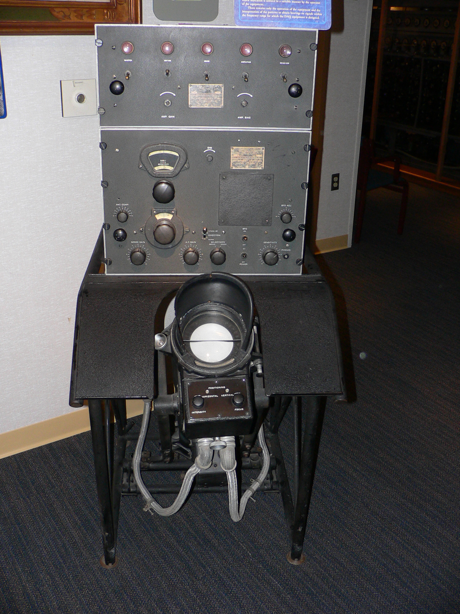

World War II US Navy high frequency radio direction finder
Radio Direction Finding works by comparing the signal strength of a directional antenna pointing in different directions. At first, this system was used by land and marine-based radio operators, using a simple rotatable loop antenna linked to a degree indicator. This system was later adopted for both ships and aircraft, and was widely used in the 1930s and 1940s. On pre-World War II aircraft, RDF antennas are easy to identify as the circular loops mounted above or below the fuselage. Later loop antenna designs were enclosed in an aerodynamic, teardrop-shaped fairing. In ships and small boats, RDF receivers first employed large metal loop antennas, similar to aircraft, but usually mounted atop a portable battery-powered receiver.
In use, the RDF operator would first tune the receiver to the correct frequency, then manually turn the loop, either listening or watching an S meter to determine the direction of the null (the direction at which a given signal is weakest) of a long wave (LW) or medium wave (AM) broadcast beacon or station (listening for the null is easier than listening for a peak signal, and normally produces a more accurate result). This null was symmetrical, and thus identified both the correct degree heading marked on the radio's compass rose as well as its 180-degree opposite. While this information provided a baseline from the station to the ship or aircraft, the navigator still needed to know beforehand if he was to the east or west of the station in order to avoid plotting a course 180-degrees in the wrong direction. By taking bearings to two or more broadcast stations and plotting the intersecting bearings, the navigator could locate the relative position of his ship or aircraft.
Later, RDF sets were equipped with rotatable ferrite loopstick antennas, which made the sets more portable and less bulky. Some were later partially automated by means of a motorized antenna (ADF). A key breakthrough was the introduction of a secondary vertical whip or 'sense' antenna that substantiated the correct bearing and allowed the navigator to avoid plotting a bearings 180 degrees opposite the actual heading. After World War II, there were many small and large firms making direction finding equipment for mariners, including Apelco, Aqua Guide, Bendix, Gladding (and its marine division, Pearce-Simpson), Ray Jefferson, Raytheon, and Sperry. By the 1960s, many of these radios were actually made by Japanese electronics manufacturers, such as Panasonic, Fuji Onkyo, and Koden Electronics Co., Ltd. In aircraft equipment, Bendix and Sperry-Rand were two of the larger manufacturers of RDF radios and navigation instruments.
[]
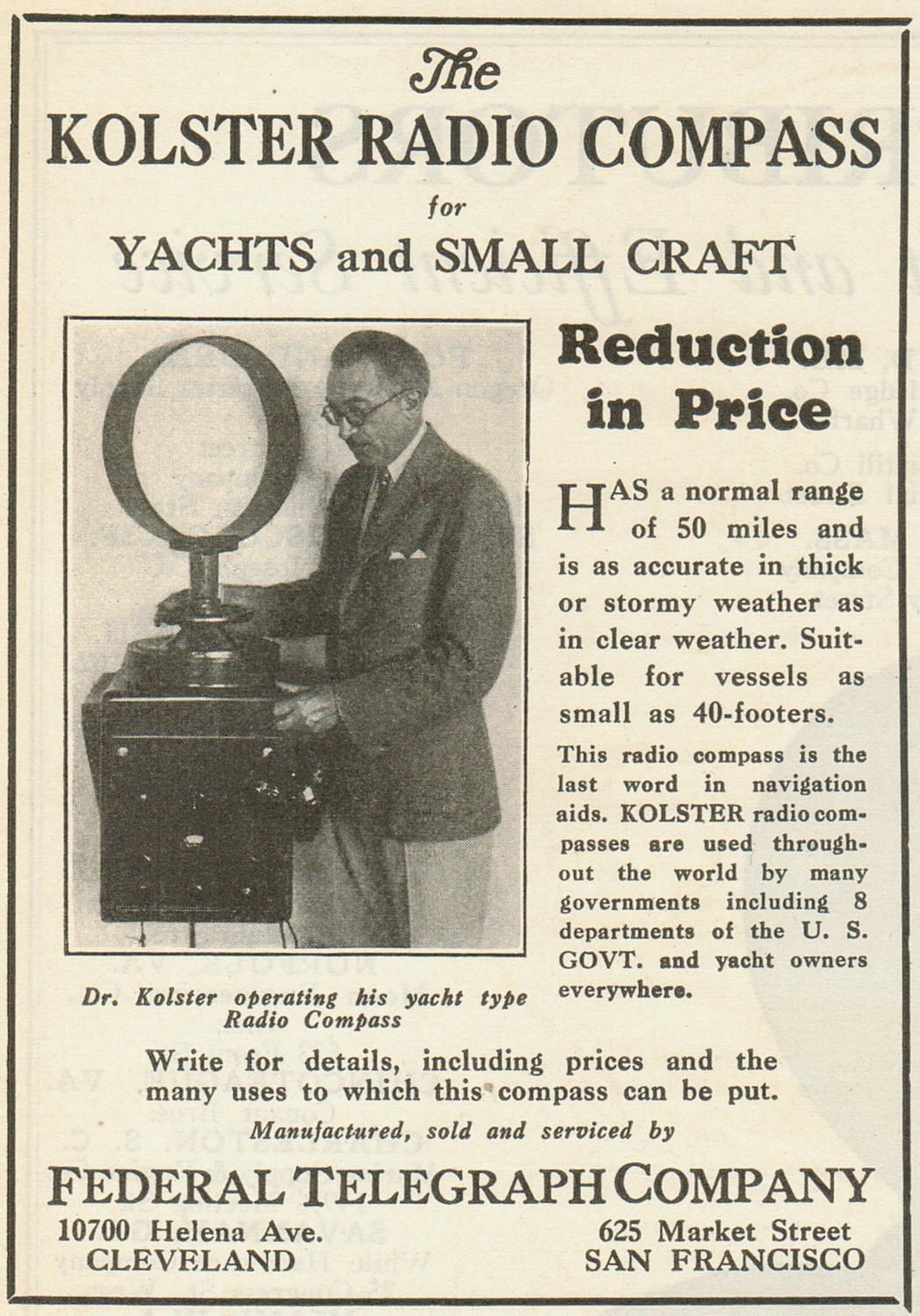

Historic advertisement for Kolster radio compass
Radio transmitters for air and sea navigation are known as beacons and are the radio equivalent to a lighthouse. The transmitter sends a Morse Code transmission on a Long wave (150 – 400 kHz) or Medium wave (520 – 1720 kHz) frequency incorporating the station's identifier that is used to confirm the station and its operational status. Since these radio signals are broadcast in all directions (omnidirectional) during the day, the signal itself does not include direction information, and these beacons are therefore referred to as non-directional beacons, or NDBs.
As the commercial medium wave broadcast band lies within the frequency capability of most RDF units, these stations and their transmitters can also be used for navigational fixes. While these commercial radio stations can be useful due to their high power and location near major cities, there may be several miles between the location of the station and its transmitter, which can reduce the accuracy of the 'fix' when approaching the broadcast city. A second factor is that some AM radio stations are omnidirectional during the day, and switch to a reduced power, directional signal at night.
RDF was once the primary form of aircraft and marine navigation. Strings of beacons formed "airways" from airport to airport, while marine NDBs and commercial AM broadcast stations provided navigational assistance to small watercraft approaching a landfall. In the United States, commercial AM radio stations were required to broadcast their station identifier once per hour for use by pilots and mariners as an aid to navigation. In the 1950s, aviation NDBs were augmented by the VOR system, in which the direction to the beacon can be extracted from the signal itself, hence the distinction with non-directional beacons. Use of marine NDBs was largerly supplanted in North America by the development of LORAN in the 1970s.
Today many NDBs have been decommissioned in favor of faster and far more accurate GPS navigational systems. However the low cost of ADF and RDF systems, and the continued existence of AM broadcast stations (as well as navigational beacons in countries outside North America) has allowed these devices to continue to function, primarily for use in small boats, as an adjunct or backup to GPS.
Automatic direction finder (ADF)[]


A teardrop-shaped housing that encases LP-21 rotatable loop antenna attached to the underside of Douglas DC-3 "Flagship Knoxville". The loop antenna is used for automatic radio compass.[7][8]
An automatic direction finder (ADF) is a marine or aircraft radio-navigation instrument that automatically and continuously displays the relative bearing from the ship or aircraft to a suitable radio station.[9][10] ADF receivers are normally tuned to aviation or marine NDBs operating in the LW band between 190 – 535 kHz. Like RDF units, most ADF receivers can also receive medium wave (AM) broadcast stations, though as mentioned, these are less reliable for navigational purposes.
The operator tunes the ADF receiver to the correct frequency and verifies the identity of the beacon by listening to the Morse code signal transmitted by the NDB. On marine ADF receivers, the motorized ferrite-bar antenna atop the unit (or remotely mounted on the masthead) would rotate and lock when reaching the null of the desired station. A centerline on the antenna unit moving atop a compass rose indicated in degrees the bearing of the station. On aviation ADFs, the unit automatically moves a compass-like pointer (RMI) to show the direction of the beacon. The pilot may use this pointer to home directly towards the beacon, or may also use the magnetic compass and calculate the direction from the beacon (the radial) at which their aircraft is located.
Unlike the RDF, the ADF operates without direct intervention, and continuously displays the direction of the tuned beacon. Initially, all ADF receivers, both marine and aircraft versions, contained a rotating loop or ferrite loopstick aerial driven by a motor which was controlled by the receiver. Like the RDF, a sense antenna verified the correct direction from its 180-degree opposite.
More modern aviation ADFs contain a small array of fixed aerials and use electronic sensors to deduce the direction using the strength and phase of the signals from each aerial. The electronic sensors listen for the trough that occurs when the antenna is at right angles to the signal, and provide the heading to the station using a direction indicator. In flight, the ADF's RMI or direction indicator will always point to the broadcast station regardless of aircraft heading, however a banked attitude can have a slight effect on the reading, the needle will still generally indicate towards the beacon, however it suffers from DIP error where the needle dips down in the direction of the turn.[Clarification needed] Such receivers can be used to determine current position, track inbound and outbound flight path, and intercept a desired bearing. These procedures are also used to execute holding patterns and non-precision instrument approaches.
Typical NDB services ranges[]
| Class of NDB | Transmission power | Effective range |
|---|---|---|
| Locator | below 25 watts | 15 NM |
| MH | below 50 watts | 25 NM |
| H | 50 to 1,999 watts | 50 NM |
| HH | 2,000+ watts | 75 NM |
Station passage[]
As an aircraft nears an NDB station, the ADF becomes increasingly sensitive, small lateral deviations result in large deflections of the needle which sometimes shows erratic left/right oscillations.[11] Ideally, as the aircraft overflies the beacon, the needle swings rapidly from directly ahead to directly behind. This indicates station passage and provides an accurate position fix for the navigator. Less accurate station passage, passing slightly to one side or another, is shown by slower (but still rapid) swinging of the needle. The time interval from the first indications of station proximity to positive station passage varies with altitude — a few moments at low levels to several minutes at high altitude.
Homing[]
The ADF may be used to home in on a station. Homing is flying the aircraft on the heading required to keep the needle pointing directly to the 0° (straight ahead) position. To home into a station, tune the station, identify the Morse code signal, then turn the aircraft to bring the ADF azimuth needle to the 0° position. Turn to keep the ADF heading indicator pointing directly ahead. Homing is regarded as poor piloting technique because the aircraft may be blown significantly or dangerously off-course by a cross-wind, and will have to fly further and for longer than the direct track.
Tracking[]
The ADF may also be used to track a desired course using an ADF and allowing for winds aloft, winds which may blow the aircraft off-course. Good pilotage technique has the pilot calculate a correction angle that exactly balances the expected crosswind. As the flight progresses, the pilot monitors the direction to or from the NDB using the ADF, adjusts the correction as required. A direct track will yield the shortest distance and time to the ADF location.
Radio-magnetic indicator (RMI)[]
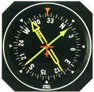

An aircraft RMI
A radio-magnetic indicator (RMI) is an alternate ADF display providing more information than a standard ADF. While the ADF shows relative angle of the transmitter with respect to the aircraft, an RMI display incorporates a compass card, actuated by the aircraft's compass system, and permits the operator to read the magnetic bearing to or from the transmitting station, without resorting to arithmetic.
Most RMI's incorporate two direction needles. Often one needle (the thicker, double-barred needle) is connected to an ADF and the other (generally thin or single-barred) is connected to a VOR. Using multiple indicators, a navigator can accurately fix the position of their aircraft without requiring station passage. Some models allow the operator to select which needle is connected to each navigation radio. There is great variation between models, and the operator must take care that their selection displays information from the appropriate ADF and VOR.
See also[]
- Acronyms and abbreviations in avionics
- Amateur radio direction finding
- Cardioid
- Battle of the Beams
- Radio navigation
- VOR/DME
- Radio direction finding
- Traffic analysis
- HF/DF
- Wullenweber
- Real time locating
Notes[]
- ↑ "Radar (Radio Direction Finding) - The Eyes of Fighter Command". http://www.battleofbritain1940.net/document-12.html.
- ↑ Yeang 2003, p. 187.
- ↑ Baker 2013, p. 150.
- ↑ Linwood 1963, p. 261.
- ↑ Yeang 2003, p. 188.
- ↑ "Broadcast Station Can Guide Flyer", April 1931, Popular Science
- ↑ AN 01-40NC-2 Handbook Erection and Maintenance Instructions. U.S. Air Force. 15 October 1944. http://www.airplanesandrockets.com/airplanes/images/C-47-Handbook-Erection-Maintenance-Antennas-Bottom.JPG. Retrieved 4 August 2014.
- ↑ May, Joseph (8 January 2013). "Flagship Knoxville — an American Airlines Douglas DC-3". Hearst Seattle Media. http://blog.seattlepi.com/travelforaircraft/2013/01/08/flagship-knoxville-%E2%80%94-an-american-airlines-douglas-dc-3/. Retrieved 3 August 2014.
- ↑ Federal Aviation Administration (2003). "Chapter 15: Navigation". Pilot's Handbook of Aeronautical Knowledge. US Dept. of Transportation. ISBN 1-56027-783-1. http://www.faa.gov/library/manuals/aviation/pilot_handbook/media/PHAK%20-%20Chapter%2015.pdf. Retrieved 11 February 2011.
- ↑ Civil Aviation Safety Authority (2005). "Operational Notes on Non-Directional Beacons (NDB) and Associated Automatic Direction Finding (ADF)" (PDF). Government of Australia. http://www.casa.gov.au/pilots/download/NDB.pdf. Retrieved 11 February 2011.
- ↑ Tait, Bob (2008). CPL Navigation. Archerfield, Queensland: Bob Tait's Aviation Theory School. OCLC 224434684.
References[]
- Boffa P. D., Sistemi per la radionavigazione, ed. Siderea, 1985
- V. Piazzi, Sistemi radioelettrici di navigazione, vol V, A.A.
- R. Trebbi, Strumenti e navigazione, ed. Aviabooks
- F. Francescotti, Avionica, ed. Aviolibri
- Alessandro Tosi, Il radiogoniometro Bellini-Tosi alla esposizione di storia della scienza in Firenze, Taranto, A. Dragone & C., 1929
- Alessandro Tosi, L' enciclopedia italiana e radiosistema a radiogoniometro, Pisa : Pacini Mariotti, 1932
- Alessandro Tosi, Contributo della marina all'avvento del radiogoniometro, Roma, E. Pinci, 1929
- Apparati R.T. di bordo e radiogoniometro, Ministero dell'Aeronautica Ispettorato Scuole, Roma, 1937
- Impiego pratico del radiogoniometro d. F. M. 3 sulle navi mercantili, Ministero delle Poste e delle telecomunicazioni, Roma, Ist. Poligr. Dello Stato, 1950
- Musella, Francesco, Il radiogoniometro ed il radiofaro nella navigazione, Roma, Ist. Poligr. Dello Stato, 1934
- Radiogoniometro Marconi per uso di bordo, tipo 11 F, Roma, tip. Radio, 1926
- Catalogo illustrato per radiogoniometro p 57 n campale, Siemens S. A., Ministero della guerra, Direzione superiore del servizio studi ed esperimenti del Genio, Milano,Tip. L. Toffaloni, 1942
- Istruzioni per l'uso dell'alimentatore Tf. 109 per radiogoniometro e ricevitore, a cura della Siemens, Ministero dell'aeronautica, Ufficio centrale delle telecomunicazioni e dell'assistenza del volo, Milano, 1941
- Catalogo illustrato per impianto radiogoniometro E 393 N., : Siemens S. n., Ministero della guerra. Direzione superiore del servizio studi ed esperimenti del genio, Milano, tip. L. Toffaloni, 1942
- 21: Il radiogoniometro Marconi per stazioni terrestri : tipo 12 A, Roma, Ufficio Marconi, 1923
Tosi, A., Il radiosistema Bellini-Tosi a radiogoniometro : l'ultima fase, Taranto, Arti Grafiche Dragone, 1930
- 23: Radiogoniometro Marconi per aeromobili : tipo 14 : codice Airder,Roma, Ufficio Marconi, e Genova, Officine radiotelegrafiche Marconi, 1923
- Il radiogoniometro e la radiotelegrafia direttiva, Ufficio Marconi, Roma, Tip. Unione Ed., 1920
- Radiogoniometro Marconi per uso di bordo : Descrizione, funzionamento, manutenzione, impiego nella condotta della navigazione, Genova : Tip. Radio, 1923
- Radiogoniometro Marconi r : G. M. 3. Istruzioni per l'uso e la manutenzione del segnale d'allarme automatico senza regolaggio tipo s. F. R, Roma : Ist. Profess. G. Marconi, 1950
- Radiogoniometro Marconi r : G. M. 3. Istruzioni per l'uso e la manutenzione del segnale d'allarme automatico senza regolaggio tipo s. F. R, Roma, Ist. Professionale di Radiotelegrafia G. Marconi, 1949
- Radiogoniometro indicatore di rotta tipo P 63 N : descrizione ed istruzioni per l'uso, Ministero dell'aeronautica, Divisione generale delle costruzioni e degli approvvigionamenti, Milano, Toffaloni, 1941
- Impiego pratico del radiogoniometro D.F.M.3 sulle navi mercantili, Ministero delle Comunicazioni, Direzione generale delle poste e dei telegrafi, Roma, Ist. Poligr. Stato, 1932
- Vincenzo Nastro, Gabriella Messina, "Navigazione radiogoniometrica", in Navigazione aerea, Milano, Hoepli, 2002, pp. 213–262. ISBN 88-203-2942-5
External links[]
| Wikimedia Commons has media related to RDF receivers. |
The original article can be found at Radio direction finder and the edit history here.