
The front suspension components of a Ford Model T.

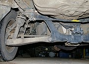
The rear suspension on a truck: a leaf spring.

Part of car front suspension and steering mechanism: tie rod, steering arm, king pin axis (using ball joints).
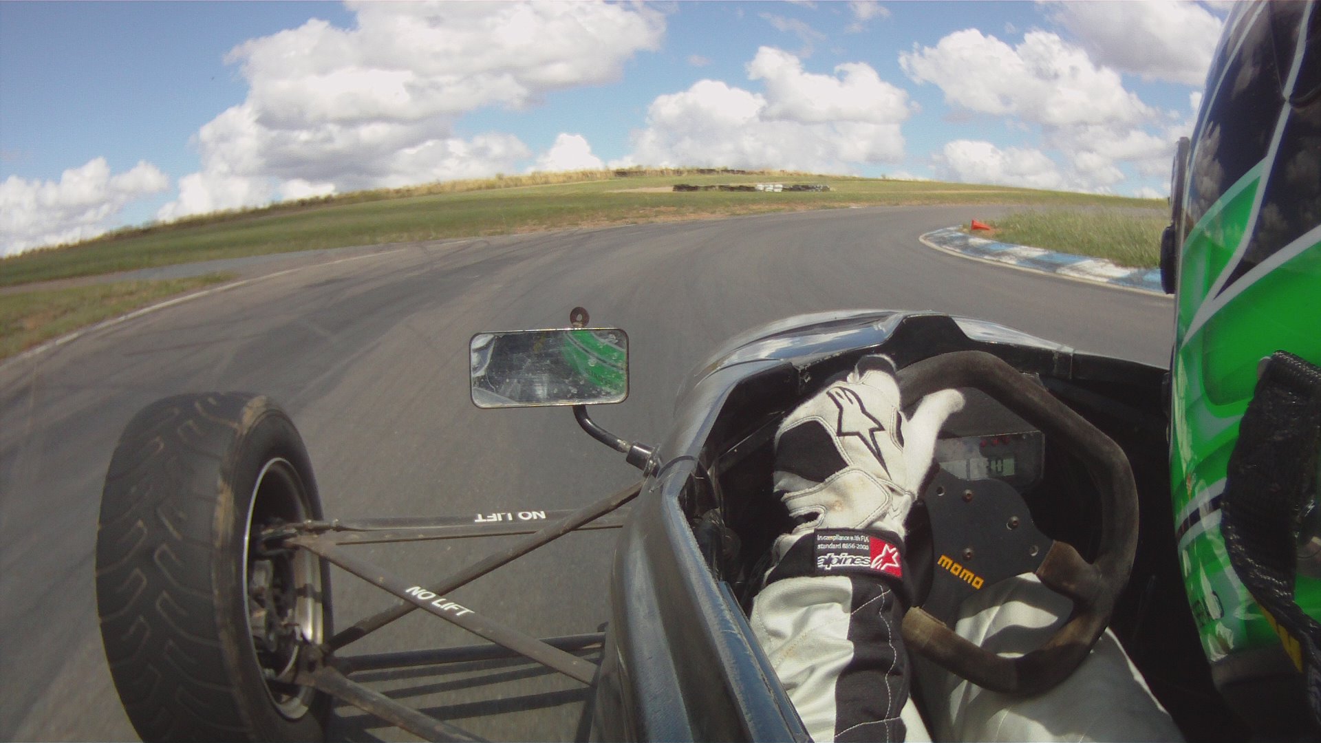

Van Diemen RF01 Racing Car Suspension.
Suspension is the term given to the system of springs, shock absorbers and linkages that connects a vehicle to its wheels and allows relative motion between the two.[1] Suspension systems serve a dual purpose — contributing to the vehicle's roadholding/handling and braking for good active safety and driving pleasure, and keeping vehicle occupants comfortable and reasonably well isolated from road noise, bumps, and vibrations,etc. These goals are generally at odds, so the tuning of suspensions involves finding the right compromise. It is important for the suspension to keep the road wheel in contact with the road surface as much as possible, because all the road or ground forces acting on the vehicle do so through the contact patches of the tires. The suspension also protects the vehicle itself and any cargo or luggage from damage and wear. The design of front and rear suspension of a car may be different.
This article is primarily about four-wheeled (or more) vehicle suspension. For information on two-wheeled vehicles' suspensions see the motorcycle suspension, motorcycle fork, bicycle suspension, and bicycle fork articles.
History[]


Strap suspension 1605
Leaf springs have been around since the early Egyptians. Ancient military engineers used leaf springs in the form of bows to power their siege engines, with little success at first. The use of leaf springs in catapults was later refined and made to work years later. Springs were not only made of metal, a sturdy tree branch could be used as a spring, such as with a bow.
An early form of suspension on ox-drawn carts had the platform swing on iron chains attached to the wheeled frame of the carriage. This system remained the basis for all suspension systems until the turn of the 19th century, although the iron chains were replaced with the use of leather straps in the 17th century.
Spring suspension[]
The first workable spring-suspension required advanced metallurgical knowledge and skill, and only became possible with the advent of industrialisation. Obadiah Elliott registered the first patent for a spring-suspension vehicle; - each wheel had two durable steel leaf springs on each side and the body of the carriage was fixed directly to the springs attached to the axles. Within a decade, most British horse carriages were equipped with springs; wooden springs in the case of light one-horse vehicles to avoid taxation, and steel springs in larger vehicles. These were often made of low-carbon steel and usually took the form of multiple layer leaf springs.[2] This was the first modern suspension system and, along with advances in the construction of roads, heralded the single greatest improvement in road transport until the advent of the automobile.[3] The British steel springs were not well suited for use on America's rough roads of the time, so the Abbot Downing Company of Concord, New Hampshire re-introduced leather strap suspension, which gave a swinging motion instead of the jolting up and down of a spring suspension.
Automobile suspension[]


Henri Fournier on his uniquely dampened and racewinning 'Mors Machine', photo taken 1902
Automobiles were initially developed as self-propelled versions of horse-drawn vehicles. However, horse-drawn vehicles had been designed for relatively slow speeds, and their suspension was not well suited to the higher speeds permitted by the internal combustion engine.
In 1901 Mors of Paris first fitted an automobile with shock absorbers. With the advantage of a dampened suspension system on his 'Mors Machine', Henri Fournier won the prestigious Paris-to-Berlin race on 20 June 1901. Fournier's superior time was 11 hrs 46 min 10 sec, while the best competitor was Léonce Girardot in a Panhard with a time of 12 hrs 15 min 40 sec.[4]
In 1920, Leyland Motors used torsion bars in a suspension system. In 1922, independent front suspension was pioneered on the Lancia Lambda and became more common in mass market cars from 1932.[5]
Important properties[]
Citroën BX Hydropneumatic suspension - maximum to minimum demonstration
Spring rate[]
The spring rate (or suspension rate) is a component in setting the vehicle's ride height or its location in the suspension stroke. When a spring is compressed or stretched, the force it exerts is proportional to its change in length. The spring rate or spring constant of a spring is the change in the force it exerts, divided by the change in deflection of the spring. Vehicles which carry heavy loads will often have heavier springs to compensate for the additional weight that would otherwise collapse a vehicle to the bottom of its travel (stroke). Heavier springs are also used in performance applications where the loading conditions experienced are more extreme.
Springs that are too hard or too soft cause the suspension to become ineffective because they fail to properly isolate the vehicle from the road. Vehicles that commonly experience suspension loads heavier than normal have heavy or hard springs with a spring rate close to the upper limit for that vehicle's weight. This allows the vehicle to perform properly under a heavy load when control is limited by the inertia of the load. Riding in an empty truck used for carrying loads can be uncomfortable for passengers because of its high spring rate relative to the weight of the vehicle. A race car would also be described as having heavy springs and would also be uncomfortably bumpy. However, even though we say they both have heavy springs, the actual spring rates for a 2,000 lb (910 kg) race car and a 10,000 lb (4,500 kg) truck are very different. A luxury car, taxi, or passenger bus would be described as having soft springs. Vehicles with worn out or damaged springs ride lower to the ground which reduces the overall amount of compression available to the suspension and increases the amount of body lean. Performance vehicles can sometimes have spring rate requirements other than vehicle weight and load.
Mathematics of the spring rate[]
Spring rate is a ratio used to measure how resistant a spring is to being compressed or expanded during the spring's deflection. The magnitude of the spring force increases as deflection increases according to Hooke's Law. Briefly, this can be stated as

where
- F is the force the spring exerts
- k is the spring rate of the spring.
- x is the deflection of the spring from its equilibrium position (i.e., when no force is applied on the spring)
Spring rate is confined to a narrow interval by the weight of the vehicle, load the vehicle will carry, and to a lesser extent by suspension geometry and performance desires.
Spring rates typically have units of N/mm (or lbf/Inch). An example of a linear spring rate is 500 lbf/in. For every inch the spring is compressed, it exerts 500 lbf. A non-linear spring rate is one for which the relation between the spring's compression and the force exerted cannot be fitted adequately to a linear model. For example, the first inch exerts 500 lbf force, the second inch exerts an additional 550 lbf (for a total of 1050 lbf), the third inch exerts another 600 lbf (for a total of 1650 lbf). In contrast a 500 lbf/in linear spring compressed to 3 inches will only exert 1500 lbf.
The spring rate of a coil spring may be calculated by a simple algebraic equation or it may be measured in a spring testing machine. The spring constant k can be calculated as follows:

.JPG)
where d is the wire diameter, G is the spring's shear modulus (e.g., about 12,000,000 lbf/in² or 80 GPa for steel), and N is the number of wraps and D is the diameter of the coil.
Wheel rate[]
Wheel rate is the effective spring rate when measured at the wheel. This is as opposed to simply measuring the spring rate alone.
Wheel rate is usually equal to or considerably less than the spring rate. Commonly, springs are mounted on control arms, swing arms or some other pivoting suspension member. Consider the example above where the spring rate was calculated to be 500 lbs/inch, if you were to move the wheel 1 in (2.5 cm) (without moving the car), the spring more than likely compresses a smaller amount. Let's assume the spring moved 0.75 in (19 mm), the lever arm ratio would be 0.75:1. The wheel rate is calculated by taking the square of the ratio (0.5625) times the spring rate, thus obtaining 281.25 lbs/inch. Squaring the ratio is because the ratio has two effects on the wheel rate. The ratio applies to both the force and distance traveled.
Wheel rate on independent suspension is fairly straightforward. However, special consideration must be taken with some non-independent suspension designs. Take the case of the straight axle. When viewed from the front or rear, the wheel rate can be measured by the means above. Yet because the wheels are not independent, when viewed from the side under acceleration or braking the pivot point is at infinity (because both wheels have moved) and the spring is directly inline with the wheel contact patch. The result is often that the effective wheel rate under cornering is different from what it is under acceleration and braking. This variation in wheel rate may be minimized by locating the spring as close to the wheel as possible.
Wheel rates are usually summed and compared with the sprung mass of a vehicle to create a "ride rate" and corresponding suspension natural frequency in ride (also referred to as "heave"). This can be useful in creating a metric for suspension stiffness and travel requirements for a vehicle.
Roll rate[]
Roll rate is analogous to a vehicle's ride rate, but for actions that include lateral accelerations, causing a vehicle's sprung mass to roll about its roll axis. It is expressed as torque per degree of roll of the vehicle sprung mass. It is influenced by factors including but not limited to vehicle sprung mass, track width, CG height, spring and damper rates, roll center heights of front and rear, anti-roll bar stiffness and tire pressure/construction. The roll rate of a vehicle can, and usually differs front to rear, which allows for the tuning ability of a vehicle for transient and steady state handling. The roll rate of a vehicle does not change the total amount of weight transfer on the vehicle, but shifts the speed at which and percentage of weight transferred on a particular axle to another axle through the vehicle chassis. Generally, the higher the roll rate on an axle of a vehicle, the faster and higher percentage the weight transfer on that axle.
Roll couple percentage[]
Roll couple percentage is a simplified method of describing lateral load transfer distribution front to rear, and subsequently handling balance. It is the effective wheel rate, in roll, of each axle of the vehicle as a ratio of the vehicle's total roll rate. It is commonly adjusted through the use of anti-roll bars, but can also be changed through the use of different springs.
Weight transfer[]
Weight transfer during cornering, acceleration or braking is usually calculated per individual wheel and compared with the static weights for the same wheels.
The total amount of weight transfer is only affected by four factors: the distance between wheel centers (wheelbase in the case of braking, or track width in the case of cornering) the height of the center of gravity, the mass of the vehicle, and the amount of acceleration experienced.
The speed at which weight transfer occurs as well as through which components it transfers is complex and is determined by many factors including but not limited to roll center height, spring and damper rates, anti-roll bar stiffness and the kinematic design of the suspension links. In most conventional applications, when weight is transferred though intentionally compliant elements such as springs, dampers and anti-roll bars, the weight transfer is said to be "elastic", while the weight which is transferred through more rigid suspension links such as A-arms and toe links is said to be "geometric".
Unsprung weight transfer[]
Unsprung weight transfer is calculated based on the weight of the vehicle's components that are not supported by the springs. This includes tires, wheels, brakes, spindles, half the control arm's weight and other components. These components are then (for calculation purposes) assumed to be connected to a vehicle with zero sprung weight. They are then put through the same dynamic loads. The weight transfer for cornering in the front would be equal to the total unsprung front weight times the G-Force times the front unsprung center of gravity height divided by the front track width. The same is true for the rear.
Sprung weight transfer[]
Sprung weight transfer is the weight transferred by only the weight of the vehicle resting on the springs, not the total vehicle weight. Calculating this requires knowing the vehicle's sprung weight (total weight less the unsprung weight), the front and rear roll center heights and the sprung center of gravity height (used to calculate the roll moment arm length). Calculating the front and rear sprung weight transfer will also require knowing the roll couple percentage.
The roll axis is the line through the front and rear roll centers that the vehicle rolls around during cornering. The distance from this axis to the sprung center of gravity height is the roll moment arm length. The total sprung weight transfer is equal to the G-force times the sprung weight times the roll moment arm length divided by the effective track width. The front sprung weight transfer is calculated by multiplying the roll couple percentage times the total sprung weight transfer. The rear is the total minus the front transfer.
Jacking forces[]
Jacking forces are the sum of the vertical force components experienced by the suspension links. The resultant force acts to lift the sprung mass if the roll center is above ground, or compress it if underground. Generally, the higher the roll center, the more jacking force is experienced.
Travel[]
Travel is the measure of distance from the bottom of the suspension stroke (such as when the vehicle is on a jack and the wheel hangs freely) to the top of the suspension stroke (such as when the vehicle's wheel can no longer travel in an upward direction toward the vehicle). Bottoming or lifting a wheel can cause serious control problems or directly cause damage. "Bottoming" can be caused by the suspension, tires, fenders, etc. running out of space to move or the body or other components of the car hitting the road. The control problems caused by lifting a wheel are less severe if the wheel lifts when the spring reaches its unloaded shape than they are if travel is limited by contact of suspension members (See Triumph TR3B.) Many off-road vehicles, such as desert racers, use straps called "limiting straps" to limit the suspensions downward travel to a point within safe limits for the linkages and shock absorbers. This is necessary, since these trucks are intended to travel over very rough terrain at high speeds, and even become airborne at times. Without something to limit the travel, the suspension bushings would take all the force when the suspension reaches "full droop", and it can even cause the coil springs to come out of their "buckets" if they are held in by compression forces only. A limiting strap is a simple strap, often nylon of a predetermined length, that stops the downward movement at a preset point before the theoretical maximum travel is reached. The opposite of this is the "bump-stop", which protects the suspension and vehicle (as well as the occupants) from violent "bottoming" of the suspension, caused when an obstruction (or hard landing) causes the suspension to run out of upward travel without fully absorbing the energy of the stroke. Without bump-stops, a vehicle that "bottoms out" will experience a very hard shock when the suspension contacts the bottom of the frame or body, which is transferred to the occupants and every connector and weld on the vehicle. Factory vehicles often come with plain rubber "nubs" to absorb the worst of the forces, and insulate the shock. A desert race vehicle, which must routinely absorb far higher impact forces, may be provided with pneumatic or hydro-pneumatic bump-stops. These are essentially miniature shock absorbers (dampeners) that are fixed to the vehicle in a location such that the suspension will contact the end of the piston when it nears the upward travel limit. These absorb the impact far more effectively than a solid rubber bump-stop will, essential because a rubber bump-stop is considered a "last-ditch" emergency insulator for the occasional accidental bottoming of the suspension; it is entirely insufficient to absorb repeated and heavy bottomings such as a high-speed off road vehicle encounters.
Damping[]
Damping is the control of motion or oscillation, as seen with the use of hydraulic gates and valves in a vehicle's shock absorber. This may also vary, intentionally or unintentionally. Like spring rate, the optimal damping for comfort may be less than for control.
Damping controls the travel speed and resistance of the vehicle's suspension. An undamped car will oscillate up and down. With proper damping levels, the car will settle back to a normal state in a minimal amount of time. Most damping in modern vehicles can be controlled by increasing or decreasing the resistance to fluid flow in the shock absorber.
Camber control[]
See dependent and independent below.
Camber changes due to wheel travel, body roll and suspension system deflection or compliance. In general, a tire wears and brakes best at -1 to -2° of camber from vertical. Depending on the tire and the road surface, it may hold the road best at a slightly different angle. Small changes in camber, front and rear, can be used to tune handling. Some race cars are tuned with -2 to -7° camber depending on the type of handling desired and the tire construction. Often, too much camber will result in the decrease of braking performance due to a reduced contact patch size through excessive camber variation in the suspension geometry. The amount of camber change in bump is determined by the instantaneous front view swing arm (FVSA) length of the suspension geometry, or in other words, the tendency of the tire to camber inward when compressed in bump.
Roll center height[]
Roll center height is a product of suspension instant center heights and is a useful metric in analyzing weight transfer effects, body roll and front to rear roll stiffness distribution. Conventionally, roll stiffness distribution is tuned adjusting antiroll bars rather than roll center height (as both tend to have a similar effect on the sprung mass), but the height of the roll center is significant when considering the amount of jacking forces experienced.
Instant center[]
Due to the fact that the wheel and tire's motion is constrained by the suspension links on the vehicle, the motion of the wheel package in the front view will scribe an imaginary arc in space with an "instantaneous center" of rotation at any given point along its path. The instant center for any wheel package can be found by following imaginary lines drawn through the suspension links to their intersection point.
A component of the tire's force vector points from the contact patch of the tire through instant center. The larger this component is, the less suspension motion will occur. Theoretically, if the resultant of the vertical load on the tire and the lateral force generated by it points directly into the instant center, the suspension links will not move. In this case, all weight transfer at that end of the vehicle will be geometric in nature. This is key information used in finding the force-based roll center as well.
In this respect the instant centers are more important to the handling of the vehicle than the kinematic roll center alone, in that the ratio of geometric to elastic weight transfer is determined by the forces at the tires and their directions in relation to the position of their respective instant centers.
Anti-dive and anti-squat[]
Anti-dive and anti-squat are percentages and refer to the front diving under braking and the rear squatting under acceleration. They can be thought of as the counterparts for braking and acceleration as jacking forces are to cornering. The main reason for the difference is due to the different design goals between front and rear suspension, whereas suspension is usually symmetrical between the left and right of the vehicle.
The method of determining the anti-dive or anti-squat depends on whether the suspension linkages react to the torque of braking and accelerating. For example, with inboard brakes and half-shaft driven rear wheels, the suspension linkages do not, but with outboard brakes and a swing-axle driveline, they do.
To determine the percentage of front suspension braking anti-dive for outboard brakes, it is first necessary to determine the tangent of the angle between a line drawn, in side view, through the front tire patch and the front suspension instant center, and the horizontal. In addition, the percentage of braking effort at the front wheels must be known. Then, multiply the tangent by the front wheel braking effort percentage and divide by the ratio of the center of gravity height to the wheelbase. A value of 50% would mean that half of the weight transfer to the front wheels, during braking, is being transmitted through the front suspension linkage and half is being transmitted through the front suspension springs.
For inboard brakes, the same procedure is followed but using the wheel center instead of contact patch center.
Forward acceleration anti-squat is calculated in a similar manner and with the same relationship between percentage and weight transfer. Anti-squat values of 100% and more are commonly used in dragracing, but values of 50% or less are more common in cars which have to undergo severe braking. Higher values of anti-squat commonly cause wheel hop during braking. It is important to note that, while the value of 100%...in either case...means that all of the weight transfer is being carried through the suspension linkage, this does not mean that the suspension is incapable of carrying additional loads (aerodynamic, cornering, etc.) during an episode of braking or forward acceleration. In other words, no "binding" of the suspension is to be implied.[6]
Flexibility and vibration modes of the suspension elements[]
In modern cars, the flexibility is mainly in the rubber bushings. For high-stress suspensions, such as off-road vehicles, polyurethane bushings are available, which offer more longevity under greater stresses. However, due to weight and cost considerations, structures are not made more ridged than necessary. Some vehicles exhibit detrimental vibrations involving the flexing of structural parts, such as when accelerating while turning sharply. Flexibility of structures such as frames and suspension links can also contribute to springing, especially to damping out high frequency vibrations. The flexibility of wire wheels contributed to their popularity in times when cars had less advanced suspensions.
Isolation from high frequency shock[]
For most purposes, the weight of the suspension components is unimportant, but at high frequencies, caused by road surface roughness, the parts isolated by rubber bushings act as a multistage filter to suppress noise and vibration better than can be done with only the tires and springs. (The springs work mainly in the vertical direction.)
Contribution to unsprung weight and total weight[]
These are usually small, except that the suspension is related to whether the brakes and differential(s) are sprung.
This is the main functional advantage of aluminum wheels over steel wheels. Aluminum suspension parts have been used in production cars, and carbon fiber suspension parts are common in racing cars.
Space occupied[]
Designs differ as to how much space they take up and where it is located. It is generally accepted that MacPherson struts are the most compact arrangement for front-engined vehicles, where space between the wheels is required to place the engine.
Inboard brakes (which reduce unsprung weight) are probably avoided more due to space considerations than to cost.
Force distribution[]
The suspension attachment must match the frame design in geometry, strength and rigidity.
Air resistance (drag)[]
Certain modern vehicles have height adjustable suspension in order to improve aerodynamics and fuel efficiency. Modern formula cars that have exposed wheels and suspension typically use streamlined tubing rather than simple round tubing for their suspension arms to reduce drag. Also typical is the use of rocker arm, push rod, or pull rod type suspensions that, among other things, place the spring/damper unit inboard and out of the air stream to further reduce air resistance.
Cost[]
Production methods improve, but cost is always a factor. The continued use of the solid rear axle, with unsprung differential, especially on heavy vehicles, seems to be the most obvious example.
Springs and dampers[]
Most conventional suspensions use passive springs to absorb impacts and dampers (or shock absorbers) to control spring motions.
Some notable exceptions are the hydropneumatic systems, which can be treated as an integrated unit of gas spring and damping components, used by the French manufacturer Citroën and the hydrolastic, hydragas and rubber cone systems used by the British Motor Corporation, most notably on the Mini. A number of different types of each have been used:
Passive suspensions[]
Traditional springs and dampers are referred to as passive suspensions — most vehicles are suspended in this manner.
Springs[]

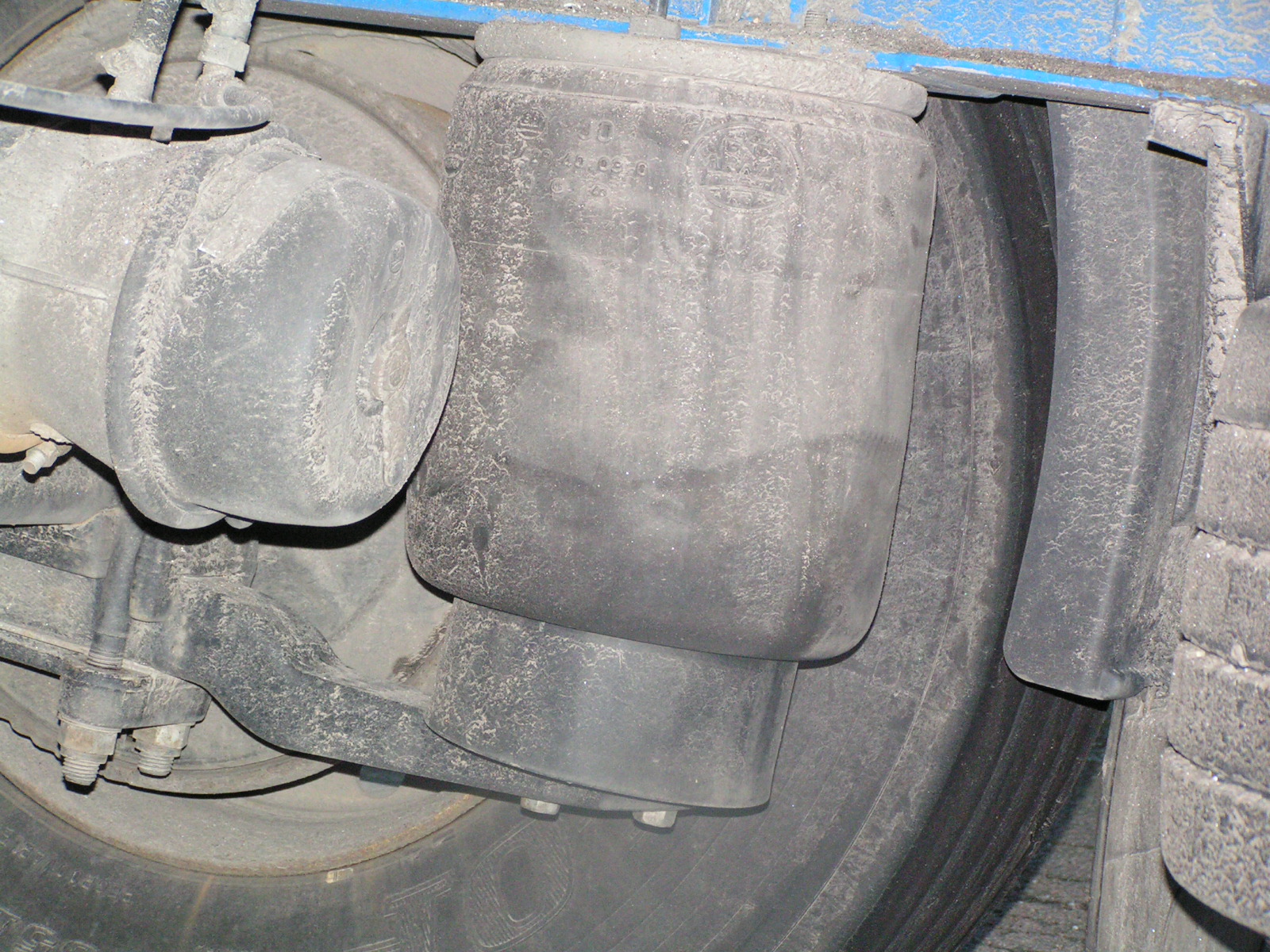
Pneumatic spring on a semitrailer
- Leaf spring – AKA Hotchkiss, Cart, or semi-elliptical spring
- Torsion beam suspension
- Coil spring
- Rubber bushing
- Air spring
Dampers or shock absorbers[]
The shock absorbers damp out the (otherwise resonant) motions of a vehicle up and down on its springs. They also must damp out much of the wheel bounce when the unsprung weight of a wheel, hub, axle and sometimes brakes and differential bounces up and down on the springiness of a tire. Some have suggested that the regular bumps found on dirt roads (nicknamed "corduroy", but properly corrugations or washboarding) are caused by this wheel bounce, though some evidence exists that it is unrelated to suspension at all. (See washboarding.)
Semi-active and active suspensions[]
If the suspension is externally controlled then it is a semi-active or active suspension — the suspension is reacting to what are in effect "brain" signals. As electronics have become more sophisticated, the opportunities in this area have expanded.
For example, a hydropneumatic Citroën will "know" how far off the ground the car is supposed to be and constantly reset to achieve that level, regardless of load. It will not instantly compensate for body roll due to cornering however. Citroën's system adds about 1% to the cost of the car versus passive steel springs.
Semi-active suspensions include devices such as air springs and switchable shock absorbers, various self-levelling solutions, as well as systems like hydropneumatic, hydrolastic, and hydragas suspensions. Mitsubishi developed the world’s first production semi-active electronically controlled suspension system in passenger cars; the system was first incorporated in the 1987 Galant model.[7][8][9][10][11] Delphi currently sells shock absorbers filled with a magneto-rheological fluid, whose viscosity can be changed electromagnetically, thereby giving variable control without switching valves, which is faster and thus more effective.
Fully active suspension systems use electronic monitoring of vehicle conditions, coupled with the means to impact vehicle suspension and behavior in real time to directly control the motion of the car. Lotus Cars developed several prototypes, from 1982 onwards, and introduced them to F1, where they have been fairly effective, but have now been banned. Nissan introduced a low bandwidth active suspension in circa 1990 as an option that added an extra 20% to the price of luxury models. Citroën has also developed several active suspension models (see hydractive). A recently publicised fully active system from Bose Corporation uses linear electric motors (i.e., solenoids) in place of hydraulic or pneumatic actuators that have generally been used up until recently. Mercedes introduced an active suspension system called Active Body Control in its the top-of-the-line Mercedes-Benz CL-Class in 1999.
Several electromagnetic suspensions have also been developed for vehicles. Examples include the electromagnetic suspension of Bose, and the electromagnetic suspension developed by prof. Laurentiu Encica. In addition, the new Michelin wheel with embedded suspension working on an electromotor is also similar.[12]
With the help of control system, various semi-active/active suspensions realize an improved design compromise among different vibrations modes of the vehicle, namely bounce, roll, pitch and warp modes. However, the applications of these advanced suspensions are constrained by the cost, packaging, weight, reliability, and/or the other challenges.
Interconnected suspensions[]
Interconnected suspension, unlike semi-active/active suspensions, could easily decouple different vehicle vibration modes in a passive manner. The interconnections can be realized by various means, such as mechanical, hydraulic and pneumatic. Anti-roll bars are one of the typical examples of mechanical interconnections, while it has been stated that fluidic interconnections offer greater potential and flexibility in improving both the stiffness and damping properties.
Considering the considerable commercial potentials of hydro-pneumatic technology (Corolla, 1996), interconnected hydropneumatic suspensions have also been explored in some recent studies, and their potential benefits in enhancing vehicle ride and handling have been demonstrated. The control system can also be used for further improving performance of interconnected suspensions. Apart from academic research, an Australian company, Kinetic, is having some success (WRC: 3 Championships, Dakar Rally: 2 Championships, Lexus GX470 2004 4x4 of the year with KDSS, 2005 PACE award) with various passive or semi-active systems, which generally decouple at least two vehicle modes (roll, warp (articulation), pitch and/or heave (bounce)) to simultaneously control each mode’s stiffness and damping, by using interconnected shock absorbers, and other methods. In 1999, Kinetic was bought out by Tenneco. Later developments by a Catalan company, Creuat has devised a simpler system design based on single-acting cylinders. After some projects on competition Creuat is active in providing retrofit systems for some vehicle models.
Historically, the first mass production car with front to rear mechanical interconnected suspension was the 1948 Citroën 2CV. The suspension of the 2CV was extremely soft — the longitudinal link was making pitch softer instead of making roll stiffer. It relied on extreme antidive and antisquat geometries to compensate for that. This redunded into a softer axle crossing stiffness that anti-roll bars would have otherwise compromised. The leading arm / trailing arm swinging arm, fore-aft linked suspension system together with inboard front brakes had a much smaller unsprung weight than existing coil spring or leaf designs. The interconnection transmitted some of the force deflecting a front wheel up over a bump, to push the rear wheel down on the same side. When the rear wheel met that bump a moment later, it did the same in reverse, keeping the car level front to rear. The 2CV had a design brief to be able to be driven at speed over a ploughed field. It originally featured friction dampers and tuned mass dampers. Later models had tuned mass dampers at the front with telescopic dampers / shock absorbers front and rear.
The British Motor Corporation was also an early adopter of interconnected suspension. A system dubbed Hydrolastic was introduced in 1962 on the Morris 1100 and went on to be used on a variety of BMC models. Hydrolastic was developed by suspension engineer Alex Moulton and used rubber cones as the springing medium (these were first used on the 1959 Mini) with the suspension units on each side connected to each other by a fluid filled pipe. The fluid transmitted the force of road bumps from one wheel to the other (on the same principle as the Citroen 2CV's mechanical system described above) and because each suspension unit contained valves to restrict the flow of fluid also served as a shock absorber.[13] Moulton went on to develop a replacement for Hydrolastic for BMC's successor, British Leyland. This system, called Hydragas worked on the same principle but instead of rubber spring units it used metal spheres divided internally by a rubber diaphragm. The top half contained pressurised gas and the lower half the same fluid as used on the Hydrolastic system. The fluid transmitted suspension forces between the units on each side whilst the gas acted as the springing medium via the diaphragm. This is the same principle as the Citroen hydropneumatic system and provides a similar ride quality but is self-contained and doesn't require an engine-driven pump to provide hydraulic pressure. The downside is that Hydragas is, unlike the Citroen system, not height adjustable or self-levelling. Hydragas was introduced in 1973 on the Austin Allegro and was used on several models, the last car to use it being the MG F in 2002.
Some of the last post-war Packard models also featured interconnected suspension.
Suspension geometry[]


Common types seen from behind; in order: *Live axle with Watt bar *Suspension like on a bike fork *Swing axle *Double wishbone *MacPherson This diagram is not exhaustive; notably excluding elements such as trailing arm links and those that are flexible.
Suspension systems can be broadly classified into two subgroups: dependent and independent. These terms refer to the ability of opposite wheels to move independently of each other.
A dependent suspension normally has a beam (a simple 'cart' axle) or (driven) live axle that holds wheels parallel to each other and perpendicular to the axle. When the camber of one wheel changes, the camber of the opposite wheel changes in the same way (by convention on one side this is a positive change in camber and on the other side this a negative change). De Dion suspensions are also in this category as they rigidly connect the wheels together.
An independent suspension allows wheels to rise and fall on their own without affecting the opposite wheel. Suspensions with other devices, such as sway bars that link the wheels in some way are still classed as independent.
A third type is a semi-dependent suspension. In this case, the motion of one wheel does affect the position of the other but they are not rigidly attached to each other. A twist-beam rear suspension is such a system.
Dependent suspensions[]
Dependent systems may be differentiated by the system of linkages used to locate them, both longitudinally and transversely. Often both functions are combined in a set of linkages.
Examples of location linkages include:
- Satchell link
- Panhard rod
- Watt's linkage
- WOBLink
- Mumford linkage
- Leaf springs used for location (transverse or longitudinal)
- Fully elliptical springs usually need supplementary location links and are no longer in common use
- Longitudinal semi-elliptical springs used to be common and still are used in heavy-duty trucks and aircraft. They have the advantage that the spring rate can easily be made progressive (non-linear).
- A single transverse leaf spring for both front wheels and/or both back wheels, supporting solid axles, was used by Ford Motor Company, before and soon after World War II, even on expensive models. It had the advantages of simplicity and low unsprung weight (compared to other solid axle designs).
In a front engine, rear-drive vehicle, dependent rear suspension is either "live axle" or deDion axle, depending on whether or not the differential is carried on the axle. Live axle is simpler but the unsprung weight contributes to wheel bounce.
Because it assures constant camber, dependent (and semi-independent) suspension is most common on vehicles that need to carry large loads as a proportion of the vehicle weight, that have relatively soft springs and that do not (for cost and simplicity reasons) use active suspensions. The use of dependent front suspension has become limited to heavier commercial vehicles.
Semi-independent suspension[]
In a semi-independent suspensions, the wheels of an axle are able to move relative to one another as in an independent suspension but the position of one wheel has an effect on the position and attitude of the other wheel. This effect is achieved via the twisting or deflecting of suspension parts under load. The most common type of semi-independent suspension is the twist beam.
- Twist beam
Independent suspension[]

A rear independent suspension on an AWD car.
The variety of independent systems is greater and includes:
- Swing axle
- Sliding pillar
- MacPherson strut/Chapman strut
- Upper and lower A-arm (double wishbone)
- Multi-link suspension
- Semi-trailing arm suspension
- Swinging arm
- Leaf springs
- Transverse leaf springs when used as a suspension link, or four quarter elliptics on one end of a car are similar to wishbones in geometry, but are more compliant. Examples are the front of the original Fiat 500, the Panhard Dyna Z and the early examples of Peugeot 403 and the back of the AC Ace and AC Aceca.
Because the wheels are not constrained to remain perpendicular to a flat road surface in turning, braking and varying load conditions, control of the wheel camber is an important issue. Swinging arm was common in small cars that were sprung softly and could carry large loads, because the camber is independent of load. Some active and semi-active suspensions maintain the ride height, and therefore the camber, independent of load. In sports cars, optimal camber change when turning is more important.
Wishbone and multi-link allow the engineer more control over the geometry, to arrive at the best compromise, than swing axle, MacPherson strut or swinging arm do; however the cost and space requirements may be greater. Semi-trailing arm is in between, being a variable compromise between the geometries of swinging arm and swing axle.
Tracked vehicles[]
Some vehicles such as trains run on long rail tracks fixed to the ground, and some such as tractors, snow vehicles and tanks run on continuous tracks that are part of the vehicle. Though either sort helps to smooth the path and reduce ground pressure, many of the same considerations apply.
Armoured fighting vehicle suspension[]


This Grant I tank's suspension has road wheels mounted on wheel trucks, or bogies.
Military AFVs, including tanks, have specialized suspension requirements. They can weigh more than seventy tons and are required to move as quickly as possible over very rough or soft ground. Their suspension components must be protected from land mines and antitank weapons. Tracked AFVs can have as many as nine road wheels on each side. Many wheeled AFVs have six or eight large wheels. Some have a Central Tire Inflation System to reduce ground loading on poor surfaces. Some wheels are too big and confined to turn, so skid steering is used with some wheeled, as well as with tracked, vehicles.
The earliest tanks of World War I had fixed suspension with no designed movement whatsoever. This unsatisfactory situation was improved with leaf spring or coil spring suspensions adopted from agricultural, automotive or railway machinery, but even these had very limited travel.
Speeds increased due to more powerful engines, and the quality of ride had to be improved. In the 1930s, the Christie suspension was developed, which allowed the use of coil springs inside a vehicle's armored hull, by changing the direction of force deforming the spring, using a bell crank. The war winning T-34 was directly descended from Christie designs. Horstmann suspension was a variation which used a combination of bell crank and exterior coil springs, in use from the 1930s to the 1990s. The bogie, but nonetheless independent, suspension of the M3 Lee/Grant and the M4 Sherman was similar to the Hortsmann type, with the suspension contained within the track oval.
By World War II the other common type was torsion bar suspension, getting spring force from twisting bars inside the hull — this sometimes had less travel than the Christie-type, but was significantly more compact, allowing more space inside the hull, with consequent possibility to install larger turret rings and thus a heavier main armament. The torsion-bar suspension, sometimes including shock absorbers, has been the dominant heavy armored vehicle suspension since World War II. Torsion bars may take space under or near the floor, which may interfere with making the tank low to reduce exposure.
As with cars, wheel travel and spring rate affect the bumpiness of the ride and the speed at which rough terrain can be negotiated. It may be significant that a smooth ride, which is often associated with comfort, increases the accuracy when firing on the move (analogously to battle ships with reduced stability, due to reduced metacentric height). It also reduces shock on optics and other equipment. The unsprung weight and track link weight may limit speed on roads and affect the life of the track and other components.
Most German WW II half tracks and their tanks introduced during the war such as the Panther tank had overlapping and sometimes interleaved road wheels to distribute the load more evenly on the track and therefore on the ground. This apparently made a significant contribution to speed, range and track life, as well as providing a continuous band of protection. It has not been used since the end of that war, probably due to the maintenance requirements of more complicated mechanical parts working in mud, sand, rocks, snow and ice, as well as to cost. Rocks and frozen mud stuck between the wheels.[14]
See also[]
- 4-poster a test rig
- 7 post shaker a test rig for high speed vehicles
- Automobile handling transverse performance
- Automotive suspension design the design process
- Active suspension powered suspension
- Bicycle fork bicycle front suspension
- Bicycle suspension especially separate springs
- Bump steer reaction to road surface
- Camber angle wheel tilt
- Caster angle self centering steering
- Chapman strut a type of rear suspension
- Citroën 2CV a successful vehicle with unusual suspension type and performance
- Classical mechanics a field of physics
- Continuous track device to reduce the ground loading of off-road
- Double wishbone suspension or A arm, maximum independent design freedom
- Kinematics physics of the geometry of motion
- MacPherson strut a type of front suspension
- Magnetic levitation and maglev train may involve superconductors
- Motorcycle fork front suspension of a motorcycle
- Multi-link suspension Multi-link suspension
- Panther tank early modern, and in ways unique heavy off-road suspension
- Roll center the axis that is not moved by a sideways force
- Scrub radius
- Shock absorber device to damp repetitive motion by absorbing energy
- Short long arms suspension or "unequal length A arm", one of the design parameters of double wishbone suspension
- Strut bar a form of semi-independent suspension
- Suspension (motorcycle) different principles than 3 or more wheels
- Sway bar or anti-roll bar, stiffens roll resistance, semi-independent
- Tire or tyre, the outer part of a wheel
- Unsprung mass the part closer to the road than the springs are
- Wheel Wheels are unsprung, except by the tires, and may flex.
References[]
- ↑ Reza N. Jazar (2008). Vehicle Dynamics: Theory and Applications. Spring. p. 455. http://books.google.com/books?id=Pvsv78xj7UIC&printsec=frontcover&dq=vehicle+dynamics&hl=en&sa=X&ei=Rr3nT8KaO4Oq2QX016jaCQ&ved=0CDcQ6AEwAA#v=onepage&q=suspension&f=false. Retrieved 2012-06-24.
- ↑ Adams, William Bridges (1837). English Pleasure Carriages. London: Charles Knight & Co.. http://books.google.co.uk/books?id=apw7AAAAMAAJ.
- ↑ "wagon and carriage". http://escola.britannica.com.br/article/277634/wagon-and-carriage?view=print.
- ↑ "The Washington Times, Sunday 30 June 1901". Chroniclingamerica.loc.gov. http://chroniclingamerica.loc.gov/lccn/sn87062245/1901-06-30/ed-1/seq-1/;words=Paris+races+Berlin+race+Race. Retrieved 2012-08-16.
- ↑ Jain, K.K.; R.B. Asthana. Automobile Engineering. London: Tata McGraw-Hill. pp. 293–294. ISBN 0-07-044529-X.
- ↑ Pages 617-620 (particularly page 619) of "Race Car Vehicle Dynamics" by William and Douglas Milliken
- ↑ "Mitsubishi Galant", Mitsubishi Motors South Africa website
- ↑ "Mitsubishi Motors history 1981-1990", Mitsubishi Motors South Africa website
- ↑ "Technology DNA of MMC", .pdf file, Mitsubishi Motors technical review 2005
- ↑ "MMC's new Galant.", Malay Mail, Byline: Asian Auto, Asia Africa Intelligence Wire, 16-SEP-02 (registration required)
- ↑ "Mitsubishi Motors Web Museum", Mitsubishi Motors website
- ↑ "Electromagnetic suspension". Amt.nl. 2008-11-19. http://www.amt.nl/web/Nieuws/Autotechniek/Tonen-Nieuws-Autotechniek/Zwevend-over-de-weg-met-magneetvering.htm. Retrieved 2012-08-16.
- ↑ "Alex Moulton Mgf Hydragas". Mgfcar.de. http://www.mgfcar.de/hydragas/moulton.htm. Retrieved 2012-08-16.
- ↑ Peter Chamberlain and Hilary Doyle, Encyclopedia of German Tanks of World War Two, 1978, 1999
External links[]
| Wikimedia Commons has media related to Automotive suspension technologies. |
- How Car Suspensions Work
- Robert W. Temple, The ABCs of Chassis Frame and Suspensions, September 1969
- Suspension Geometry Calculator
The original article can be found at Suspension (vehicle) and the edit history here.